


Industrial circuit breakers
-
Turbo guide: how to select an industrial moulded-case circuit breaker (MCCB)
An industrial moulded-case circuit breaker (MCCB, moulded case circuit breaker) protects cables and equipment against overload and short circuit. It is designed for higher currents than a miniature circuit breaker, and its ultimate breaking capacity Icu in this group ranges from 18 to 85 kA, depending on the model. A correctly selected breaker works for years. One chosen “by eye” either trips constantly or, worse still, fails to trip when it must.
Blue – information Green – benefit to you Orange – ⚠ check Red – ⚡ safety and mistakesContents- What do you need? Quick selection
- Miniature circuit breaker or MCCB?
- Selection in 4 steps
- FMC frames and currents
- Icu and Ics – what’s the difference
- Thermal-magnetic or electronic trip unit
- Tripping characteristics and time–current curve
- Accessories: contacts, releases, motor operator, terminals
- ⚠ What to check before buying
- ✗ Most common mistakes
- Diagram: selectivity wrong / right
- FAQ
What do you need? Quick selection
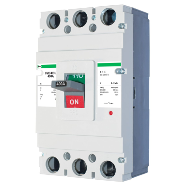
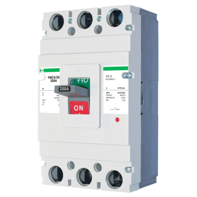
Situation Solution Where to look Separate feeder up to 100 A (pump, fan, small board) FMC1 (16 or 40 A, Icu 25 kA) or FMC2 (80 or 100 A, Icu 35–36 kA) 40 A · 100 A Board or high-power equipment feeder 100–250 A FMC3, Icu 50 kA (100, 125, 160, 200, 225, 250 A) 160 A · 250 A Building, farm or workshop incomer 250–400 A FMC4, Icu 50 kA (250, 315, 350, 400 A) 400 A FMC4 Transformer substation outgoing feeder, large incomer 400–800 A FMC5 (400, 500, 630 A, Icu 50 kA) or FMC6 (800 A) 630 A · 800 A Precise coordination with the cable or generator, or selectivity, is required Electronic trip unit: 250 A (Ir1 100–250 A) or 400 A (160–400 A, in 1 A steps, Icu 85 kA) 250 A · 400 A The breaker is mounted inside the enclosure, but must be operated through the door Circuit breaker with rotary (door-mounted) handle 50 A, IP40 Status must be visible in the control room, or the breaker must be tripped remotely or by a fire alarm signal Auxiliary / alarm contacts, shunt trip, motor operator – by frame Accessories table ↓ What you gain by selecting correctly- The cable does not overheat, and the breaker does not trip for no reason under normal load.
- During a short circuit the breaker safely interrupts the current and, if Ik does not exceed Ics, remains fit for further service.
- With selectivity, only the faulty feeder trips – not the whole building.
- Accessories (contacts, releases, motor operator) fit straight away, as they are selected for the same frame.
Miniature circuit breaker or MCCB?
Feature Miniature circuit breaker (MCB) Industrial MCCB Standard EN 60898-1 (household and similar use) IEC/EN 60947-2 (industrial equipment) Current Usually up to 63–125 A In this group 16–800 A Breaking capacity Typically 4.5 / 6 / 10 kA In this group Icu 18–85 kA Mounting DIN rail Usually bolted to a mounting plate, connected with cables or busbars Accessories and adjustment Limited Contacts, releases, motor operator; adjustable settings on electronic models Simple rule: if the current exceeds 125 A, or the short-circuit current at the point of installation exceeds the MCB’s breaking capacity (e.g. close to a transformer) and cascade (back-up) protection per the manufacturer’s tables is not ensured – you need an MCCB.Selection in 4 steps
1. Current In
Ib ≤ In ≤ Iz: load current ≤ breaker rated current ≤ cable current-carrying capacity→2. Icu
Icu ≥ maximum short-circuit current Ik at the point of installation→3. Trip unit
Thermal-magnetic or adjustable electronic→4. Accessories and connection
Contacts, releases, motor operator, terminals – for the same frameHow to calculate the load current (3-phase, 400 V)
Ib = P / (√3 × U × cos φ). Example (general load, not a motor): 110 kW, cos φ 0.9 → 110,000 / (1.732 × 400 × 0.9) ≈ 176 A. A 200 A breaker is suitable if the cable current-carrying capacity Iz is at least 200 A.
For motors: Ib = P / (√3 × U × cos φ × η), or take the rated current from the motor nameplate. The starting current is 6–8 times the rated current, so the instantaneous protection threshold must be above the starting peak – otherwise the breaker will trip when the motor starts.FMC frames and currents
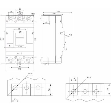
The frame determines the dimensions, terminal size and which accessories fit. Always select accessories by the frame designation (FMC1–FMC6), not just by current.
Frame Currents in the group Icu (400 V) Typical location FMC1 16, 40 A 25 kA Separate feeders, equipment FMC2 80, 100 A 35–36 kA Sub-distribution boards FMC3 100–250 A 50 kA Workshop boards, high-power equipment FMC4 250–400 A 50 kA Building incomers FMC5 400–630 A 50 kA Large incomers, substation outgoing feeders FMC6 800 A see product page Transformer substation outgoing feeder ⚠ 400 A is available in both the FMC4 and FMC5 frames. FMC5 is larger, its terminals are wider and its accessories are different. If you plan to increase capacity to 500–630 A in future or connect heavy cables, choose FMC5.Icu and Ics – what’s the difference
Icu – ultimate breaking capacity
The maximum short-circuit current the breaker can interrupt. After such an interruption the breaker may be damaged and unfit for further use – it must be inspected or replaced.Ics – service breaking capacity
The current after interrupting which the breaker remains fit for further service. Stated in kA or as % of Icu (e.g. 50 %, 75 %, 100 %).Example from our product page: FMC3 160 A – Icu 50 kA, Ics 25 kA (400 V). If Ik = 20 kA at the point of installation, this breaker is suitable even on the basis of Ics. For critical incomers (hospitals, production lines), choose a breaker with Ics ≥ Ik.
How to quickly estimate Ik at a transformer
Ik ≈ In(transf.) × 100 / uk %, where In = S / (√3 × U). Example: 630 kVA, 400 V, uk 6 % → In = 630,000 / (1.732 × 400) ≈ 909 A → Ik ≈ 909 × 100 / 6 ≈ 15 kA directly at the transformer terminals. This is an upper limit – the calculation ignores the impedance of the high-voltage network. The further along the cable, the lower Ik. Oil-immersed 630 kVA transformers often have uk = 4 % – then Ik ≈ 23 kA. The Ik values of transformers operating in parallel add up. The exact value is provided by the designer or the network operator.Thermal-magnetic or electronic trip unit
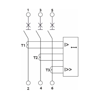
Level What it is Suitable for Thermal-magnetic (FMC1–FMC6 series) The thermal element protects against overload, the electromagnetic element against short circuit. Settings are usually fixed (on some models the thermal element is adjustable – see product page). Most feeders and incomers where there are no special selectivity requirements Electronic (250 A and 400 A with LCD) A microprocessor measures the current; settings are adjustable. The 250 A model has long-time (L), short-time delay (S) and instantaneous (I) protection; for the 400 A model functions, see the product page. Incomers, generators, where coordination with the cable or selectivity is required Settings of the adjustable 250 A breaker per product page: Ir1 100–250 A, t1 12–150 s, short-time protection Ir2 2–12 × Ir1 with delay t2 0.06–0.3 s, instantaneous Ir3 4–14 × Ir1. The long-time protection of the 400 A breaker is adjustable 160–400 A, in 1 A steps. For other settings, see the product page.
Tripping characteristics: how to read the time–current curve
The curve shows how long the breaker takes to trip at a given current. Both axes are logarithmic. On the left – small overloads that the breaker tolerates for minutes or hours; on the right – a short circuit, which it interrupts within hundredths of a second.
Illustration to explain the principle – not the curve of a specific model. The exact curve can be found in the manufacturer’s datasheet.
Zone What happens What it means in practice 1 – Thermal (overload) Per IEC/EN 60947-2: at 1.05 × In the breaker does not trip; at 1.30 × In it trips within 1 h (In ≤ 63 A) or 2 h (In > 63 A). The greater the overload, the faster it trips. Short overloads (starting, peaks) do not cause trouble; a sustained overload is cleared before the cable overheats 2 – Instantaneous (short circuit) Once the Im (Ii) threshold is exceeded, the breaker trips without intentional delay – within ~10–20 ms. For thermal-magnetic distribution MCCBs the threshold is typically about 10 × In, with a tolerance usually of ±20 %. The short-circuit current at the end of the feeder must exceed Im with a margin L-S-I (electronic) L – long-time (Ir, t1), S – short-time delay (Isd, t2), I – instantaneous (Ii). Each threshold and time can be set. The curve can be “shifted” to suit the cable, generator or downstream breakers Comparison with miniature circuit breakers (EN 60898-1)
Characteristic Instantaneous tripping Typical load B 3–5 × In Long feeders, lighting, sockets, low starting currents C 5–10 × In General purpose, small motors, LED with drivers D 10–20 × In Transformers, compressors, high starting currents Thermal-magnetic MCCB Typically ~10 × In (fixed or adjustable – see manufacturer’s data) Distribution boards, incomers, high-power equipment MCCBs are not designated by the letters B/C/D: their instantaneous protection threshold is stated as a multiple of In (e.g. 10 × In) or, on electronic models, is set by the user.
⚠ Long feeder – check the minimum short-circuit current
A fault at the end of the feeder must be cleared by the instantaneous protection. Therefore the minimum short-circuit current at the end of the feeder (Ik min, phase–PE) must exceed Im with a tolerance margin (≈ 1.2 × Im). Example: 160 A breaker with Im ≈ 10 × In = 1600 A → Ik min ≥ ~1920 A is required. If the cable is long and Ik min is lower, the breaker will clear the fault by the thermal element only – within seconds or longer. In that case: a larger cable, an electronic breaker with a lower Isd / Ii, or a designer’s solution.We do not currently state the exact Im multiple and curve for FMC thermal-magnetic breakers on the product pages. If your project requires them – ask us and we’ll send the manufacturer’s data.Accessories: contacts, releases, motor operator, terminals
Accessory What it does Frames in the group Auxiliary contact Indicates the breaker position (on / off) – for an indicator lamp, PLC, control room FMC1–FMC5 (1NO+1NC, left- and right-hand), FMC6 (2NO+2NC, left-hand) Alarm contact Signals that the breaker has gone to the “tripped” position – due to overload, short circuit or a shunt trip command. It does not signal manual switching off FMC1, FMC3, FMC4 (left-hand), FMC2 (right-hand) Shunt trip (230 V) Trips the breaker on a remote command (fire alarm system, dispatcher). Requires a reliable control supply; for emergency stopping, where the breaker must trip on loss of voltage, choose a solution per the design (e.g. an undervoltage release) FMC2–FMC6 Motor operator (230 V) Motor drive – switches the breaker on and off remotely (ATS, control-room operation) FMC1–FMC4 Spreader / extension terminals Spreader – for connecting larger cables or busbars; extension (straight) – extend the terminals FMC2–FMC6, set of 3 pcs ⚠ Left-hand and right-hand accessories are mounted on different sides of the breaker. Before ordering, check which side is free and how many accessories fit in the same frame. If the accessory you need for your frame is not listed – ask us and we’ll order it.⚠ What to check before buying
 Kibirkštis: “They said 250 A was needed, so I took 250 A. Nobody told me the cable was too thin for that current…”
What to check Why Cable current-carrying capacity Iz The breaker protects the cable: In must not exceed Iz Short-circuit current Ik at the point of installation Icu must not be lower – otherwise the breaker may fail to clear the fault Voltage and number of poles FMC breakers are 3P – the neutral (N) is not switched by the breaker. Icu depends on voltage: at 690 V it is lower than at 400 V Cable cross-section and terminal size A heavy cable may not fit – spreader terminals are available for this Frame (FMC1–FMC6) for accessories An accessory for another frame will not fit – accessories are not universal Ambient temperature in the switchboard The operating range is usually −25…+55 °C. Thermal protection is calibrated at the temperature stated by the manufacturer (often +30 or +40 °C) – in a hotter board it will trip earlier, so a current derating factor applies ✗ Most common mistakes
Mistake Consequence Breaker selected by load without checking the cable The cable overheats, but the breaker does not trip Icu too low close to a transformer The breaker may disintegrate during a short circuit Incoming and outgoing breakers with the same current rating Both may trip during a fault – the entire site loses power Accessories ordered by current rather than by frame They do not fit and have to be returned and reordered Shunt trip supply taken downstream of the same breaker On loss of supply the shunt trip cannot operate, and after tripping the alarm and automation systems no longer work. Supply it from a reliable source (upstream of the breaker, UPS, 24 V DC) Long feeder: Ik at the end of the feeder lower than the instantaneous protection threshold Im The fault is cleared by the thermal element only – within seconds or longer; danger to people and the cable ⚡ Terminals not tightened or under-tightened The contact heats up, insulation burns, and a fire may start  ⚡ Safe installation – Fazė’s tip
Install the breaker only after isolating it and verifying that there is no voltage. Lock off the incomer (LOTO). Tighten the terminals to the torque specified by the manufacturer using a torque wrench. Cable lugs must match the cross-section and terminal width. After commissioning, under load, it is worth checking the connections with a thermal imaging camera – you will spot an overheating contact before it burns out. Work must be carried out by a qualified electrician.☝ Elsprendimai.eu recommends- Don’t know the actual load? Rent a network analyser and measure before replacing the incomer.
- Overheating connections in a switchboard will be revealed by a thermographic inspection.
- Need an assembled switchboard? We’ll assemble it to your diagram.
- For remote tripping (e.g. from a fire alarm system), order together a shunt trip and an alarm contact for the same frame.
Diagram: selectivity – wrong and right
Kibirkštis: “One compressor failed, and the whole workshop went dark. Why?”
Fazė: “Because the incoming breaker tripped together with the feeder breaker. Look at the diagram.”✗ WRONG① Incomer 250 A, thermal-magnetic↓② Feeder 250 AFeeder 100 AFeeder 100 A↓ ⚡ short circuit③ Both ② and ① trip✓ RIGHT① Incomer 250 A, electronic: S with delay, I – maximum setting↓② Feeder 100 AFeeder 100 AFeeder 40 A↓ ⚡ short circuit③ Only ② trips, the other feeders keep runningWhy – explanation by diagram numbers- Wrong ①–②: both breakers have the same current rating and both have instantaneous protection only. The short-circuit current exceeds the instantaneous threshold of both, so both trip almost simultaneously.
- Wrong ③: when the incomer trips, the healthy feeders also lose power.
- Right ①: the ratio of incomer to feeder current ratings is at least ~2 (250 A / 100 A = 2.5). The incomer’s short-time protection (S) operates with a delay (e.g. t2 0.1–0.2 s), and the instantaneous protection (I) is set to maximum. Within the delay time the feeder breaker has time to clear the fault.
- Right ②–③: only the faulty feeder trips – but only as long as the fault current does not exceed the incomer’s instantaneous protection threshold. For this 250 A breaker that is at most 14 × Ir1 ≈ 3.5 kA. When Ik is higher (close to a transformer often 10–25 kA), the incomer will trip too: in that case selectivity is ensured only by the manufacturer’s selectivity tables or by design.
⚠ The diagram is for guidance only. Check settings and wiring against the manufacturer’s instructions and the design. Installation is carried out by, and is the responsibility of, a qualified electrician. UAB „Elektrotechnikos sprendimai“ accepts no liability for connection or possible errors.FAQ
Kibirkštis: The feeder needs 250 A – will a miniature circuit breaker do?
Fazė: No. Miniature circuit breakers are usually rated up to 125 A, so a 250 A current requires an MCCB. Most importantly, In must not exceed the cable current-carrying capacity, and Icu must not be lower than the short-circuit current at that point.
Kibirkštis: What is the difference between Icu and Ics?
Fazė: Icu is the maximum current the breaker can interrupt, but it may be damaged afterwards. Ics is the current after interrupting which it remains fit for service. Icu is stated on the product page; if Ics is not stated – ask us and we’ll confirm it.
Kibirkštis: 400 A is available in both FMC4 and FMC5. Which one should I choose?
Fazė: If 400 A will be enough in future too and the cables are standard – FMC4. If you plan to expand to 500–630 A or connect larger cables and busbars – FMC5. The accessories for the two frames are different.
Kibirkštis: Can I also switch the neutral with the same breaker?
Fazė: No, FMC breakers are 3-pole. If the design requires the neutral to be switched, you need a 4P breaker – ask us and we’ll make an offer.
Kibirkštis: When is it worth paying more for an electronic trip unit?
Fazė: When the breaker protects an incomer, generator or transformer, when precise coordination with the cable is required, or when selectivity is important. For a separate feeder, thermal-magnetic is usually sufficient.
Kibirkštis: Which characteristic – B, C or D – do these breakers have?
Fazė: The letters B/C/D designate miniature circuit breakers. The MCCB instantaneous protection threshold is stated as a multiple of In – for thermal-magnetic distribution breakers typically about 10 × In, i.e. roughly between C and D. On electronic breakers you set it yourself.
Kibirkštis: What is the difference between an auxiliary contact and an alarm contact?
Fazė: An auxiliary contact shows whether the breaker is on or off. An alarm contact signals that the protection or the shunt trip has operated – it does not signal manual switching off. This lets the dispatcher immediately distinguish a fault from a planned shutdown.
Sources: IEC/EN 60947-2 (low-voltage circuit breakers); IEC 60364-4-43 (protection against overcurrent, Ib ≤ In ≤ Iz); EN 60898-1 (miniature circuit breakers); technical data from elsprendimai.eu product pages (FMC3 160 A, FMC3E 250 A, FMC4Ei 400 A). Checked 2026-10-15.
Send us your diagram – we’ll select the breaker and accessories
State the load, cable and transformer rating or Ik. We’ll reply with the frame, Icu and accessories you need, and give you a price.
Get a quote →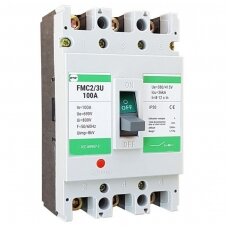 1 - 16 of 29
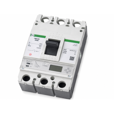
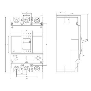
 Price 592.90 € VAT incl.( 490.00 € VAT excl. )
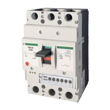
 Industrial circuit breaker | 3P | 250A | 50kA | adjustable | IP20 | Promfactor Baltic | FMC3ECode: FMC3EPrice 164.00 € VAT incl.( 135.54 € VAT excl. )
 Price 169.82 € VAT incl.( 140.35 € VAT excl. )
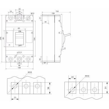 Price 104.04 € VAT incl.( 85.98 € VAT excl. )
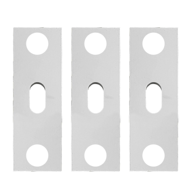
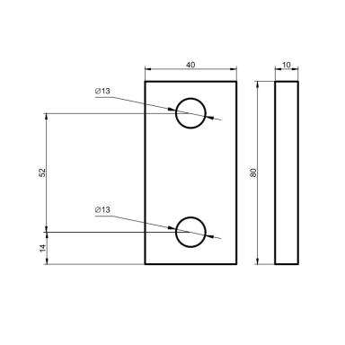 Price 40.69 € VAT incl.( 33.63 € VAT excl. )
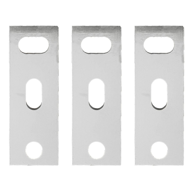
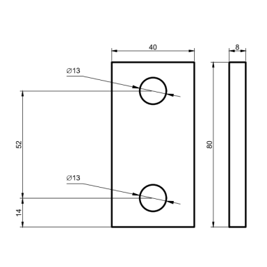 Price 35.01 € VAT incl.( 28.93 € VAT excl. )
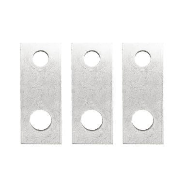
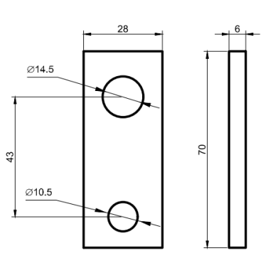 Price 19.46 € VAT incl.( 16.08 € VAT excl. )
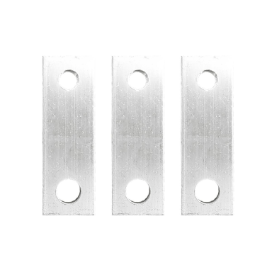
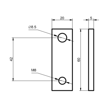 Price 9.56 € VAT incl.( 7.90 € VAT excl. )
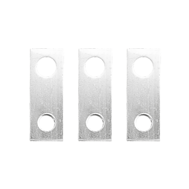
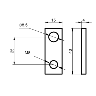 Price 4.61 € VAT incl.( 3.81 € VAT excl. )
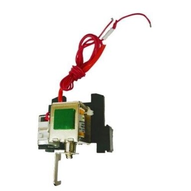 Independent shunt release (right) for industrial circuit breakers FMC6 (FMD) | 230V | Promfactor Baltic F/SH6230RCode: F/SH6230RPrice 29.39 € VAT incl.( 24.29 € VAT excl. )
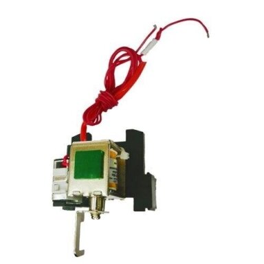 Independent shunt release (right) for industrial circuit breakers FMC5 (FMD) | 230V | Promfactor Baltic F/SH5230RCode: F/SH5230RPrice 18.98 € VAT incl.( 15.69 € VAT excl. )
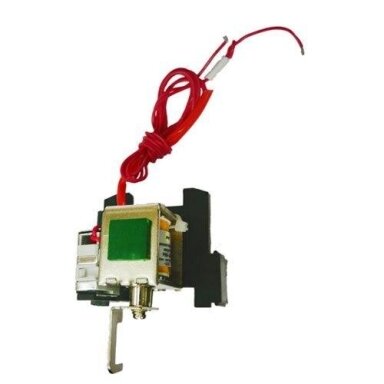 Independent shunt release (right) for industrial circuit breakers FMC4 (FMD) | 230V | Promfactor Baltic F/SH4230RCode: F/SH4230RPrice 17.19 € VAT incl.( 14.21 € VAT excl. )
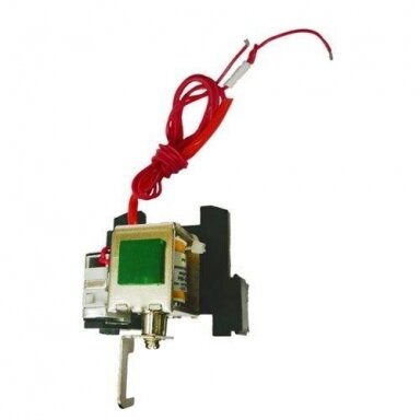 Independent shunt release (right) for industrial circuit breakers FMC3 (FMD) | 230V | Promfactor Baltic F/SH3230RCode: F/SH3230RPrice 5.66 € VAT incl.( 4.68 € VAT excl. )
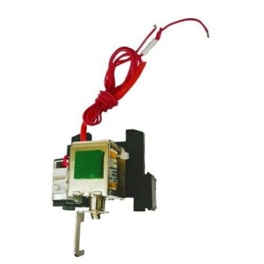 Independent shunt release (right) for industrial circuit breakers FMC2 (FMD) | 230V | Promfactor Baltic F/SH2230RCode: F/SH2230RPrice 4.82 € VAT incl.( 3.98 € VAT excl. )
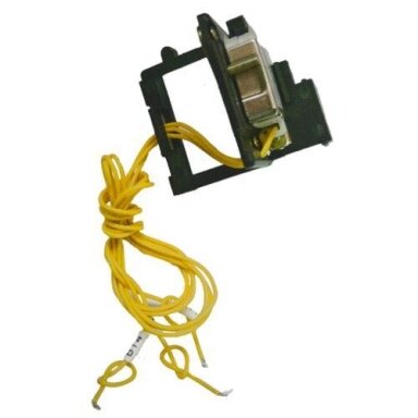 Price 10.48 € VAT incl.( 8.66 € VAT excl. )
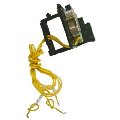 Price 4.57 € VAT incl.( 3.78 € VAT excl. )


