
Lightning protection | grounding system components | rods | connectors | fastening | installation accessories
-
Lightning protection guide: how to build a system that really works
Here you will find a quick selection by situation, protection zones in metres, a diagram of the complete system with explanations, material compatibility, the most common mistakes and answers to the key questions.
Colour coding: ■ information · ■ benefit, solution · ■ ⚠ check · ■ ⚡ safety, mistakes
Contents: What do you need? · Protection zones · Complete system · Materials · What to check · Mistakes · FAQ · SourcesWhat do you need? Quick selection
Situation Solution Where to find House with a pitched roof Passive air terminal on the ridge, 2 down conductors Ø8 mm, test joints, type A earth electrode, T1+T2 in the main board Passive, Wire, Rods Flat roof without penetrations Air terminals and masts on concrete bases, concrete-filled conductor holders Concrete bases, Holders Large warehouse, farm, open area Active (ESE) lightning rod on a mast – a large radius with a single air terminal Active, Masts Rooftop solar power plant Modules within the zone, separation distance s from air terminals and down conductors (EN 62305-3), DC and AC SPDs T2 SPDs, Air terminals Hard or stony soil Threaded rods with pointed driving tips, driving head for a rotary hammer Driving tips, Driving heads Measurement and maintenance required Inspection box with a test joint for each down conductor, lightning strike counter Inspection boxes, Counters Joints in the ground Exothermic welding or anti-corrosion tape Exothermic welding, Strips Protect electronics in the house T1+T2 at the service entrance, T2 in the sub-board, T3 at the equipment, data line SPDs T1+T2, T2/T3 The entire chain from one catalogue – compatible materials and diameters
A lightning protection system is only as strong as its weakest joint. We offer masts, conductor wire, holders, connectors, inspection (test) boxes and earthing that are matched to Ø8 mm wire and Ø14.2–20 mm rods – no more guessing whether it will “fit”. Send us the building dimensions or design – we will select the kit.
How many metres does a lightning rod protect
The protection zone depends on three things: how far the tip of the air terminal rises above the protected surface (h), the protection class (I–IV) and the type of lightning rod. The tables show the zone radius at the level of the protected surface, in metres.
Protection classes (EN 62305-3)
Class Rolling sphere radius R Air-termination mesh size Typical spacing between down conductors I 20 m 5 × 5 m 10 m II 30 m 10 × 10 m 10 m III 45 m 15 × 15 m 15 m IV 60 m 20 × 20 m 20 m The class is determined by the designer based on a risk assessment (EN 62305-2). Class III or IV is most commonly used for residential houses.
Passive (Franklin) lightning rod – radius r, m
h above surface Class I Class II Class III Class IV 1 m 6 8 9 11 2 m 9 11 13 15 3 m 11 13 16 19 4 m 12 15 19 22 5 m 13 17 21 24 6 m 14 18 22 26 8 m 16 20 26 30 10 m 17 22 28 33 Rolling sphere method (EN 62305-3): r = √(h·(2R − h)), single air terminal above a flat surface. A taller object on the roof (chimney, antenna) fits into the zone with a smaller radius. For wider roofs, several air terminals or an air-termination mesh are combined.
Active (ESE) lightning rods – protection radius Rp, m, at h = 5 m
Model ΔT, µs I II III IV Manufacturer's catalogue FOREND F10120 (PETEX-S) 30 48 55 63 71 – FOREND F10105 (EU-M) 45 63 71 81 89 – FOREND F10117 (PETEX-M) 45 63 71 81 89 – FOREND F10110 (EU) 60 79 86 97 107 – FOREND F10115 (PETEX-L) 60 79 86 97 107 – LAP CX-040 22 39 46 54 61 Rp 53 m LAP CX-070 31 49 56 65 72 Rp 65 m LAP BX-125 40 58 65 75 84 Rp 74 m LAP BX-175 63* 79 86 97 107 Rp 100 m LAP AX-210 82* 79 86 97 107 Rp 120 m LAP DX-250 96* 79 86 97 107 Rp 134 m NF C 17-102:2011: Rp = √(h·(2r − h) + ΔL·(2r + ΔL)) for h ≥ 5 m; for h from 2 to 5 m, Rp = h·Rp(5)/5. ΔL (m) = ΔT (µs), r = 20 / 30 / 45 / 60 m (I–IV). * A maximum of 60 µs is used in the calculation, so for models with a higher ΔT the Rp shown here is lower than in the manufacturer's catalogue. The catalogue Rp is the manufacturer's data under the conditions it specifies.
How Rp changes with height (Class III / IV), m
h above surface ΔT 30 µs ΔT 45 µs ΔT 60 µs 2 m 25 / 28 32 / 36 39 / 43 3 m 38 / 43 48 / 54 58 / 64 4 m 51 / 57 64 / 72 78 / 85 5 m 63 / 71 81 / 89 97 / 107 6 m 64 / 72 81 / 90 97 / 107 8 m 65 / 73 82 / 91 98 / 108 10 m 66 / 75 83 / 92 99 / 109 How to calculate: for a house with a pitched roof and a chimney, you install a passive air terminal so that its tip is 3 m above the ridge. For Class III, r ≈ 16 m at ridge level: this covers a ridge about 32 m long if the air terminal is in the middle. An active lightning rod with ΔT 60 µs and its tip 5 m above the protected roof surface gives Rp ≈ 97 m for Class III – a single unit can protect a large warehouse or farm. Find lightning rods here: passive, active (ESE).
⚠ Important note on active lightning rods: The EN 62305 series does not cover ESE lightning rods; they are designed according to the French standard NF C 17-102. Whether ESE is suitable is decided by the designer and the client. The ESE tip must be at least 2 m above the protected surface.Diagram: the complete system from top to ground
A lightning rod diverts a direct strike to the ground, but part of the lightning current reaches power, antenna and data lines through the earthing system and service entries. That is why external lightning protection is always complemented by surge protective devices (SPDs) – the purple LPZ zones show how each stage reduces the stress. The numbers in the diagram correspond to the explanations below it.
 KibirkštisWe've installed and earthed the lightning rod – is that enough?
 FazėNo, it isn't. The lightning rod protects the building from a direct strike, while the electronics inside are protected by T1+T2, T2 and T3 SPDs and the main equipotential bonding busbar. Look at the diagram – from 1 to 15.
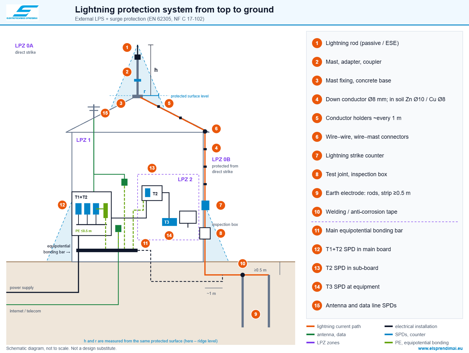 ☝ Click the diagram to open an enlarged version.⚠ The diagram is for guidance only and may contain inaccuracies. It does not replace a lightning protection design.
The protection class, air terminal positions, number of down conductors and separation distances are determined by the designer. The qualified electrician carrying out the installation is responsible for it. UAB „Elektrotechnikos sprendimai“ is not liable for the installation or possible errors.Why – explanations by diagram number
1Lightning rod
✗ An air terminal “just to have one”; a chimney or antenna protrudes from the zone.
✓ Height selected according to the zone table; all rooftop equipment within the zone.
Why: The rolling sphere “touches” everything that protrudes from the zone – that is where lightning strikes. For Class III, R = 45 m (EN 62305-3).
2Mast, adapter, coupler
✗ Mast too tall without guy wires, mismatched diameters.
✓ Height according to the zone, manufacturer's adapter and coupler, guy wires for taller masts.
Why: Every extra metre increases the wind moment on the fixing. Lightning current flows through every joint – each one must be mechanically and electrically reliable.
Products: masts · couplers, guy wires
3Fixing
✗ Mast fixed at a single point, flat roof penetrated.
✓ At least two fixing points; on a flat roof – a concrete base with a rubber mat.
Why: Penetrating the waterproofing = a leak. A concrete base stays in place by its own weight, and the mat protects the roofing.
Products: holders · concrete bases
4Down conductor
✗ Thin wire, loops, aluminium straight into the ground.
✓ Ø8 mm (50 mm²) along the shortest path; before entering the ground – transition to Ø10 mm galvanized steel wire (or 30 × 3.5 mm strip) or Ø8 mm copper.
Why: Minimum cross-section 50 mm² (EN 62305-3, EN 62561-2). A loop increases inductance and overvoltage. Aluminium corrodes in the ground, and galvanized steel in the ground requires a larger cross-section – Ø10 mm (78 mm²).
5Conductor holders
✗ Holders every 2–3 m, the wire sags and rubs against the roofing.
✓ Approximately every 1 m, correct Ø8 mm slot, concrete-filled on a flat roof.
Why: Electrodynamic forces of the lightning current and wind move an unsecured wire. A loose fit in the slot allows the wire to expand with temperature.
Products: conductor holders
6Connectors
✗ Wires twisted together, copper directly on galvanized steel.
✓ Cross and parallel connectors; Cu–Zn via a stainless steel spacer.
Why: A twisted joint cannot withstand kA currents. Copper and zinc form a galvanic couple – the zinc dissolves.
Products: cross connectors · mast connectors
7Lightning strike counter
✗ No way to know whether lightning has struck the system.
✓ Counter on the down conductor above the test joint.
Why: Joints must be checked after every strike. For active lightning rod systems, a counter is required by NF C 17-102.
Products: counters
8Test joint
✗ Down conductor welded to the earth electrode – nothing to disconnect.
✓ A disconnectable test joint for each down conductor, in an inspection box.
Why: Without disconnecting it, you cannot measure the earth electrode resistance separately. The test joint is required by EN 62305-3.
Products: inspection boxes
9Earth electrode
✗ A single short rod “wherever was convenient”.
✓ Type A: a separate electrode for each down conductor (for Class III–IV horizontal ≥5 m or vertical ≥2.5 m), at least two in total; or type B: a ring at ≥0.5 m depth, ~1 m from the wall.
Why: Recommended resistance is less than 10 Ω. The lower the resistance, the less lightning current “looks for” another path – through the installation.
Products: rods · couplers · driving tips · driving heads
10Joints in the ground
✗ Unprotected bolted joint in the ground.
✓ Exothermic welding or a bolt with anti-corrosion tape.
Why: Moisture and salts in the ground eat away an unprotected joint within a few years – resistance rises and the system “breaks” unnoticed.
Products: exothermic welding · anti-corrosion tapes
11Equipotential bonding
✗ Separate lightning protection earth electrode not connected to the building's earthing.
✓ All earth electrodes and metal service entries connected to the main equipotential bonding busbar.
Why: Lightning current in the earth electrode raises its potential by kilovolts. If the building's earthing is at a different potential, a dangerous voltage appears between appliances.
Products: equipotential bonding busbars
12T1+T2 at the service entrance
✗ There is a lightning rod, but the board has only T2 or nothing.
✓ T1 (usually T1+T2) in the main board, Iimp selected by design, leads up to 0.5 m.
Why: Part of the lightning current (10/350 µs) flows from the earth electrode through equipotential bonding and SPDs along the incoming conductors into the grid – only T1 can withstand such a current (EN 62305-4, HD 60364-5-534).
Products: T1 / T1+T2 SPDs
13T2 in the sub-board
✗ One SPD at the service entrance, with equipment 20–30 m of cable away.
✓ An additional T2 in a sub-board located further from the service entrance.
Why: An SPD effectively protects about 10 m of cable. Further along the cable, the overvoltage can double due to reflections.
Products: T2 SPDs
14T3 at the equipment
✗ A plug-in “extension lead with protection” without T2 in the board.
✓ T3 in the socket or at the equipment, with T2 installed upstream.
Why: T3 is designed to suppress the residual surge after T2 – on its own it will not absorb lightning energy.
Products: T2/T3 SPDs
15Antenna and data
✗ Antenna above the zone, coaxial cable without SPD, LAN unprotected.
✓ Antenna within the zone (LPZ 0B), mast bonded to the lightning protection system or installed at separation distance s; coaxial and data line SPDs at the equipotential bonding busbar.
Why: Through antenna and LAN cables, the overvoltage goes straight into the TV, router and cameras.
Products: data line SPDs
Material compatibility
Connected to → Aluminium Copper Galvanized steel Stainless steel Aluminium ✓ ✗ bimetallic connector only ✓ ✓ Copper ✗ bimetallic connector only ✓ ✗ via a stainless steel spacer ✓ Galvanized steel ✓ ✗ via a stainless steel spacer ✓ ✓ In the ground ✗ not suitable ✓ ✓ (joints protected) ✓ On concrete, plaster ⚠ only via a holder with a gap ✓ ✓ ✓ Based on the material usage guidance of EN 62305-3 and EN 62561. Copper above a galvanized surface (e.g. copper wire above a galvanized roof) also promotes corrosion – water washes copper ions onto the zinc.
⚠ What to check before buying
KibirkštisBefore buying, I always write down these points – then the kit is complete the first time.What to check Why it matters Protection class and zone They determine the air terminal height, the number of down conductors and the distances. Building perimeter Number of down conductors = perimeter ÷ spacing according to class (10–20 m), but no fewer than two. Roof covering and structure This determines the holder type: press-in, concrete-filled, screw-on. Wire material Aluminium – on the roof and walls (on plaster and concrete only via holders with a gap); into the ground – Ø10 mm galvanized steel wire or Ø8 mm copper. Soil type Sand, clay or stones determine the length, number and tips of the rods. One box per down conductor A test joint and an inspection box for each down conductor. SPDs in the board With external lightning protection, T1 or T1+T2 is required at the service entrance – check what is installed now. ✗ Most common mistakes
Mistake Consequence Aluminium wire buried in the ground Disintegrates within a few years – the system breaks unnoticed. No test joint You cannot measure the earth electrode resistance without digging or dismantling. Copper directly on galvanized steel Galvanic corrosion – the joint loosens. Chimney, antenna or solar modules outside the zone Lightning strikes the unprotected equipment. Down conductor with loops and sharp bends Inductance increases, flashover to structures is possible. Separate lightning protection earth electrode not connected to the main equipotential bonding busbar ⚡ Dangerous potential difference between appliances and pipes. There is a lightning rod, but no T1 SPD in the board ⚡ Part of the lightning current enters the electrical installation – risk of fire and equipment damage.
⚡ Safe installation – advice from Fazė
- Never work on the roof or on down conductors when a thunderstorm is approaching.
- Work at height – only with fall protection.
- Before driving rods, find out the routes of underground cables and pipes.
- Measure the earth electrode resistance after installation and periodically; record the results.
- SPDs in the board must be connected by a qualified electrician with the power disconnected.
☝ Elsprendimai.eu recommends: complement external lightning protection with T1+T2 SPDs in the main board, T2 and T3 SPDs in sub-boards and at the equipment, and make joints in the ground by exothermic welding. See also: passive and active (ESE) lightning rods.Frequently asked questions
Questions are asked by Kibirkštis – a young, curious electrician who dares to ask what others don't. Answers come from Fazė – an experienced engineer.
KibirkštisHow many down conductors does my house need?
FazėDivide the building perimeter by the typical spacing for the class: 15 m for Class III, 20 m for Class IV. For example, a 12 × 10 m house (perimeter 44 m) in Class III: 44 ÷ 15 ≈ 3 down conductors. In any case, no fewer than two – at opposite corners of the building.
KibirkštisPassive or active lightning rod?
FazėFor a house or a small building, a passive one is usually sufficient – it is simple and recognised by EN 62305. An active (ESE) rod suits large open areas where a large radius is needed from a single air terminal. Note: ESE is designed according to NF C 17-102 and is not covered by EN 62305 – the designer decides.
KibirkštisWhat should the earth electrode resistance be?
FazėLess than 10 Ω is recommended. It is measured with the test joint disconnected. If you cannot achieve it, extend the rods (joining them with couplers) or add electrodes – don't “fix” it with salt.
KibirkštisCan aluminium wire be used?
FazėYes, on the roof and walls – Ø8 mm aluminium is light and easy to work with. But not in the ground and not directly on plaster or concrete: above ground level, at the test joint, switch to Ø10 mm galvanized steel wire or Ø8 mm copper.
KibirkštisWill a lightning rod protect my TV and boiler?
FazėNot on its own. A lightning rod protects the building from a direct strike, while electronics need SPDs: T1+T2 at the service entrance, T2 in the sub-board and T3 at sensitive equipment. SPDs for antenna and LAN lines are also needed.
KibirkštisDo you help select the complete kit?
FazėYes. Send us the building dimensions, roof type or design – we will select air terminals, down conductors, holders, connectors, earthing and SPDs. Contact us.Sources
- EN 62305-1…4 – Protection against lightning (general principles, risk management, physical damage to structures, electrical and electronic systems within structures).
- EN 62561 series – Lightning protection system components (LPSC).
- EN 61643-11 / -21 – Surge protective devices for power and telecommunication lines; HD 60364-5-534 – selection and erection of SPDs.
- NF C 17-102:2011 – Early streamer emission (ESE) lightning protection systems.
The zone tables were calculated using the formulas of the cited standards. Checked on 2026-10-07.
Gap-free lightning protection – from air terminal to distribution board
Air terminals, masts, conductor wire, holders, connectors, inspection (test) boxes, earthing, exothermic welding and surge protective devices – all in one place. Send us the building dimensions or design: we will select a compatible kit and prepare a quote.
Get a quote


