


Mini contactors for electric motor control
-
⚡ Compact mini contactors for motor, lighting and automation control
- ⚡ Most commonly from 6A to 32A
⚡ AC and DC control coils: 24V, 230V, 400V, etc.
⚡ Models for DIN rail or panel mounting
⚡ Suitable for pumps, fans, compressors and heating systems
⚡ Auxiliary contacts, thermal relays and mechanical interlocks available
⚡ For professional and residential electrical control solutions
-
Mini contactors – for compact motor, lighting, heating and automation control
Mini contactors are compact electrical control devices designed for switching loads on and off and for automatic control in electrical cabinets, equipment, building automation and industrial systems. They are used to control motors, pumps, fans, lighting, heating equipment and other electrical loads when reliability, compact size and convenient installation are important.
Main idea:
A mini contactor is selected when it is necessary to reliably control an electrical load remotely, automatically or manually, but space in the electrical cabinet is limited. It is a practical solution for smaller motors, lighting groups, heating systems, ventilation and automation circuits.Control voltage
24V DC, 230V AC, 400V AC, etc.Current range
Usually 6A-32AContacts
1P, 2P, 3P, 4P, NO / NCMounting
DIN rail or mounting plateWhat is a mini contactor?
A mini contactor is an electromagnetic switching device that switches an electrical circuit on or off according to a control signal. When control voltage is applied to the contactor coil, the contacts switch and activate the connected load. When the coil power supply is interrupted, the contactor contacts return to their initial position.
Such devices are especially useful when a load needs to be controlled not directly with a switch, but through automation: a timer, thermostat, pressure relay, PLC controller, control push buttons, motion sensors or another control signal.
Important to know:
A contactor itself is usually not complete motor protection. It is intended for switching the load on and off. For motors, motor protection, a thermal relay or an electronic protection relay is often used additionally.Mini contactor structure
- Electromagnetic coil – the control part that switches the contactor on when it receives control voltage.
- Main power contacts – switch the main load: motor, lighting, heater or another device.
- Auxiliary contacts – used for signalling, indication, self-holding circuits or PLC control.
- Moving contact system – physically connects or disconnects the contacts.
- Arc extinguishing area – helps interrupt the electric arc more safely during switching.
- Terminals for wire connection – can be screw, spring or push-in type.
Technical data
Product type Mini contactor Purpose Control of electrical loads, motors, lighting, heating and automation circuits Rated current Usually from 6A to 32A, depending on the model Rated voltage AC 230V, AC 400V, DC 24V or another value according to the specific model Control coil voltage 24V DC, 24V AC, 110V AC, 230V AC, 400V AC, etc. Number of contacts 1P, 2P, 3P, 4P or combined main and auxiliary contacts Contact types NO – normally open, NC – normally closed Utilisation categories AC-1, AC-3, AC-4, AC-7a, AC-7b, AC-15 or others according to the model Protection class Usually IP20, installed in an electrical cabinet or protected enclosure Mounting On DIN rail or mounting plate, depending on the model Connection type Screw, spring or push-in type terminals Recommended contactor selection table by A and kW
Important:
This table is for recommendation purposes only and is intended for preliminary selection when only the motor current in amperes or only the power in kilowatts is known. The exact contactor must always be selected according to the motor nameplate, rated current, voltage, utilisation category, starting conditions, operating mode and manufacturer’s technical data.Motor power at 400V AC-3 Approximate motor current Recommended AC-3 contactor size 0.37 kW approx. 1 A 6A or the nearest higher AC-3 contactor 0.75 kW approx. 2 A 6A or the nearest higher AC-3 contactor 1.1 kW approx. 2.5-3 A 6A or 9A AC-3 contactor 1.5 kW approx. 3.5-4 A 6A or 9A AC-3 contactor 2.2 kW approx. 5 A 9A AC-3 contactor 3 kW approx. 6-7 A 9A or 12A AC-3 contactor 4 kW approx. 8-9 A 9A or 12A AC-3 contactor 5.5 kW approx. 11-12 A 12A or 18A AC-3 contactor 7.5 kW approx. 15-16 A 18A or 25A AC-3 contactor 11 kW approx. 21-23 A 25A or 32A AC-3 contactor How to use the table?- If only the motor power in kW is known, the table helps to preliminarily understand what contactor current may be required.
- If only the motor current in A is known, it is possible to approximately estimate what motor power it may correspond to.
- For motors, the AC-3 category is always evaluated, not only the general AC-1 current.
- The actual motor current may differ due to motor efficiency, cos φ, speed, starting conditions and manufacturer.
- If the load is started frequently, operates under difficult conditions or has a high starting current, it is recommended to choose a contactor with reserve.
Most common contactor coil voltages
Coil voltage Where is it most commonly used? 24V DC PLC, automation controllers, safe control circuits, industrial automation systems 24V AC Control circuits, transformer-based controls, building automation solutions 230V AC The most common choice in simple control, lighting, heating and building automation systems 400V AC When the control signal is taken from a three-phase system, if provided for in the electrical diagram Note:
The contactor coil voltage must match the control circuit voltage. For example, a contactor with a 230V AC coil will not operate from a 24V DC control signal, so before ordering it is necessary to check the electrical diagram or control circuit voltage.Utilisation categories: AC-1, AC-3 and others
Category What does it mean? Where is it used? AC-1 Resistive or slightly inductive load Heaters, resistive loads, simple electrical circuits AC-3 Motor starting and switching off during normal operation Pumps, fans, compressors, three-phase motors AC-4 Frequent starting, braking, reversing or impulse control Reversing and intensive-switching motor circuits AC-7a Household resistive or slightly inductive loads Household heating, lighting or similar devices AC-7b Household motor loads Small pumps, fans, household motors Connection types and terminals
- Screw terminals – a traditional and widely used solution. The wire is clamped with a screw, so it is important to follow the tightening torque specified by the manufacturer.
- Spring terminals – faster installation, lower risk of loosening due to vibration, convenient in automation cabinets.
- Push-in terminals – allow the wire to be inserted quickly, often reducing installation time and the likelihood of installation errors.
 1 - 16 of 17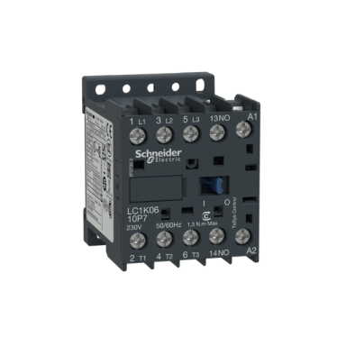
 LP1K mini contactor | 3P | 12A | 5.5kW | 24 V DC coil | 1NO auxiliary contact | for electric motors and control circuitsCode: LP1K1210BDPrice 28.41 € VAT incl.( 23.48 € VAT excl. )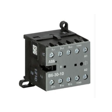
 Mini contactor | 3P | 20A | 4kW | 220-240VAC | 3NO | ABB | B6-30-10-80Code: B6-30-10-80Price 18.23 € VAT incl.( 15.06 € VAT excl. )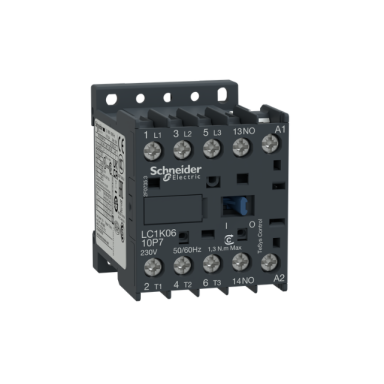
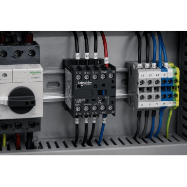 LC1K mini contactor | 3P | 16A | 7.5kW | 24VAC coil | 1NO auxiliary contact | for electric motor and control circuitsCode: LC1K1610B7Price 33.02 € VAT incl.( 27.29 € VAT excl. )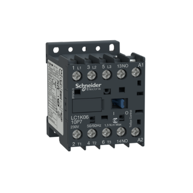
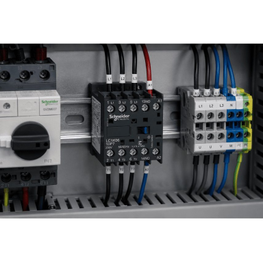 LC1K mini contactor | 3P | 6A | 2.2kW | 230VAC coil | 1NO auxiliary contact | for electric motors and control circuitsCode: LC1K0610P7Price 18.92 € VAT incl.( 15.64 € VAT excl. )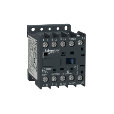
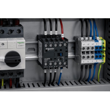 LC1K mini contactor | 3P | 6A | 2.2kW | 24VAC coil | 1NO auxiliary contact | for electric motors and control circuitsCode: LC1K0610B7Price 15.42 € VAT incl.( 12.74 € VAT excl. )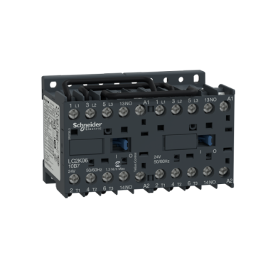
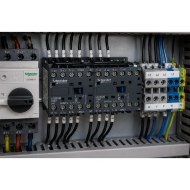 LC2K reversing mini contactor | 3P | 12A | 5.5kW | 230VAC coil | 1NO auxiliary contact | for electric motors and control circuitsCode: LC2K1210P7Price 51.46 € VAT incl.( 42.53 € VAT excl. )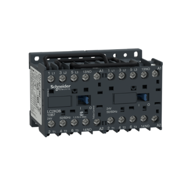
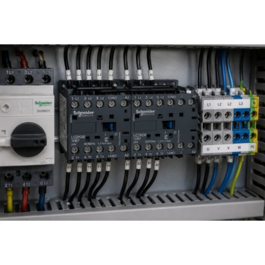 LC2K Reversing Mini Contactor | 3P | 16A | 7.5kW | 230VAC Coil | 1NO Auxiliary Contact | For Electric Motors and Control CircuitsCode: LC2K1610P7Price 63.03 € VAT incl.( 52.09 € VAT excl. )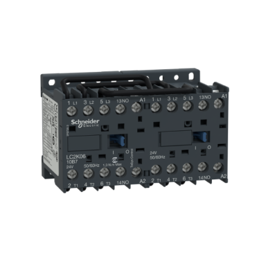
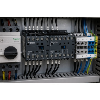 LC2K Reversing Mini Contactor | 3P | 6A | 2,2kW | 230VAC Coil | 1NO Auxiliary Contact | For Electric Motors and Control CircuitsCode: LC2K0610P7Price 44.95 € VAT incl.( 37.15 € VAT excl. )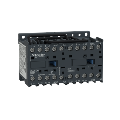
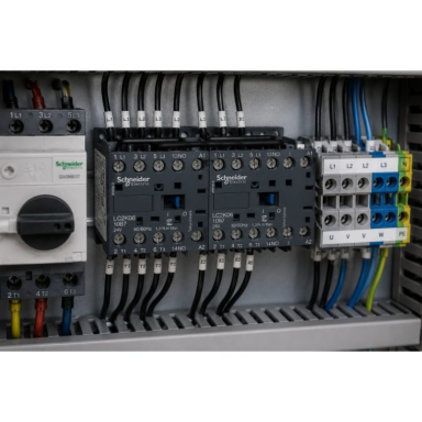 LC2K Reversing Mini Contactor | 3P | 9A | 4kW | 230VAC Coil | 1NO Auxiliary Contact | For Electric Motors and Control CircuitsCode: LC2K0910P7Price 45.82 € VAT incl.( 37.87 € VAT excl. )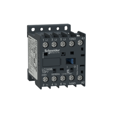
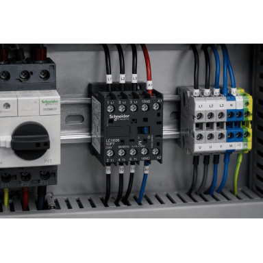 LP1K mini contactor | 3P | 6A | 2,2kW | 24VAC coil | 1NO auxiliary contact | for electric motors and control circuitsCode: LP1K0610BD1Price 23.23 € VAT incl.( 19.20 € VAT excl. )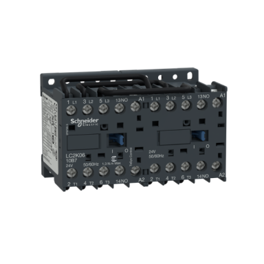
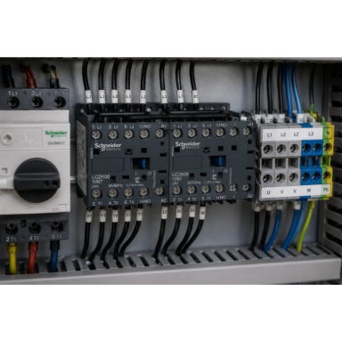 LP2K Reversing Mini Contactor | 3P | 12A | 5.5kW | 24VAC Coil | 1NO Auxiliary Contact | For Electric Motors and Control CircuitsCode: LP2K1210BDPrice 68.53 € VAT incl.( 56.64 € VAT excl. )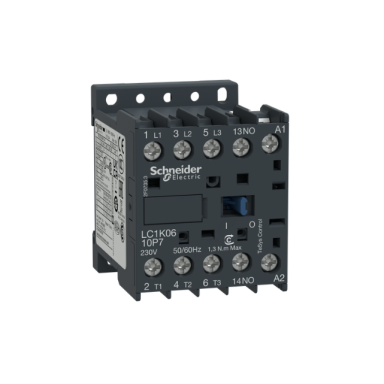
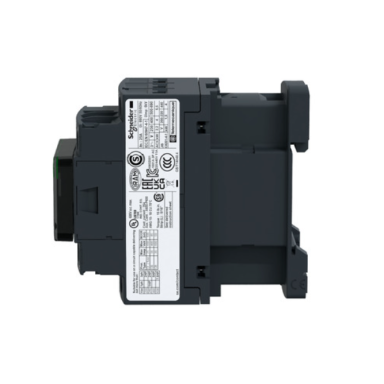 LC1K mini contactor | 3P | 12A | 5.5kW | 24VDC coil | 1NO auxiliary contact | for electric motors and control circuitsCode: LC1K12106BLS207Price 52.10 € VAT incl.( 43.06 € VAT excl. )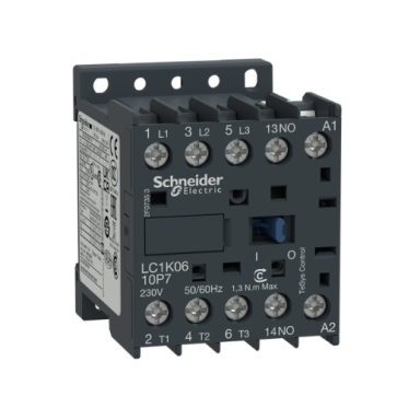
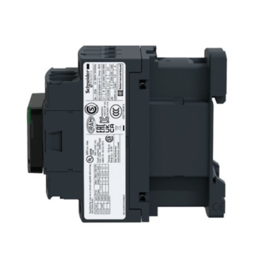 LC1K mini contactor | 3P | 9A | 4kW | 230VAC coil | 1NO auxiliary contact | for electric motors and control circuitsCode: LC1K0910P7Price 18.92 € VAT incl.( 15.64 € VAT excl. )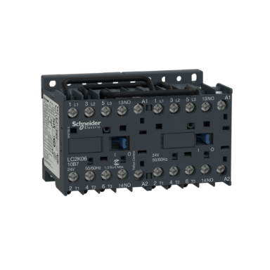
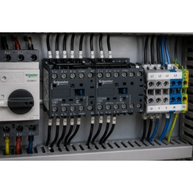 LP2K reversing mini contactor | 3P | 6A | 2.2kW | 24VDC coil | 1NO auxiliary contact | for electric motors and control circuitsCode: LP2K0610BDPrice 55.64 € VAT incl.( 45.98 € VAT excl. )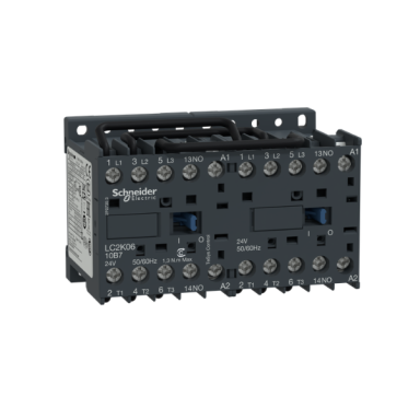
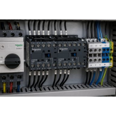 LP2K reversing mini contactor | 3P | 9A | 4kW | 24VDC coil | 1NO auxiliary contact | for electric motors and control circuitsCode: LP2K0910BDPrice 65.79 € VAT incl.( 54.37 € VAT excl. )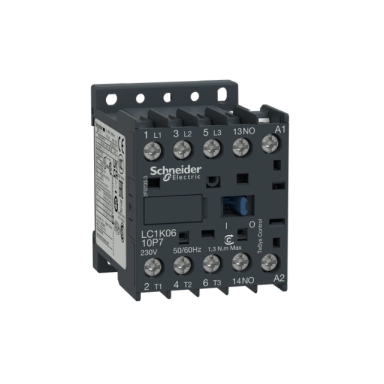
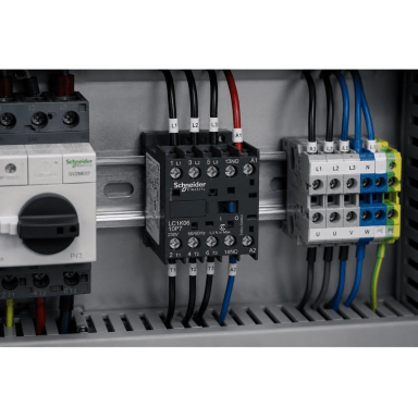 LC1K mini contactor | 3P | 12A | 5.5kW | 230VAC coil | 1NO auxiliary contact | for electric motor and control circuitsCode: LC1K1210P7Price 24.19 € VAT incl.( 19.99 € VAT excl. )


