
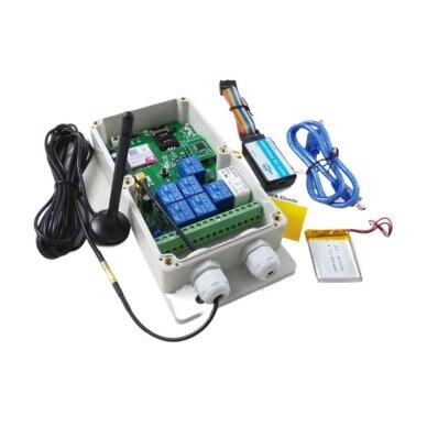
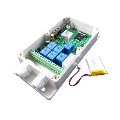
GSM remote control relay | 7 channels | 230VAC/30VDC | 10A | NO + COM | SMS and call control
Code: U4.0-201501Price 250.17 € VAT incl.( 206.75 € VAT excl. )Buy more, pay less10+ pcs. – 223.85 € for pcs. -10%Want another price? Suggest yours!GSM-RELAY – a 7-channel GSM remote control module designed to control electrical and automation circuits using a mobile phone. OUT1 can be controlled by a phone call, while all 7 relays can be controlled via SMS commands; the maximum load of each output is 230 V AC / 10 A or 30 V DC / 10 A. The controller supports up to 200 phone numbers, features 6-digit password protection, and operates on 9–12 V AC/DC.
-
GSM remote control relay | 7 channels | 230 V AC / 10 A | SMS and call control | whitelist up to 200 numbers | GSM-RELAY
GSM-RELAY – an electronic 7-channel GSM remote control module with an integrated GSM modem, designed for remote switching of electrical equipment and control circuits using a mobile phone. Control is performed by phone call or SMS commands, allowing the device to be operated from any location where compatible GSM communication is available.
The controller has 7 separate relay outputs. The first relay channel can be controlled by a phone call, while all relay outputs can be controlled by SMS commands. When controlling the first relay by call, it is possible to select either a momentary pulse or toggle ON/OFF mode.
Each relay output has NO and COM contacts. The maximum contact load of one output is 230 V AC / 10 A or 30 V DC / 10 A. The load must be powered from a separate electrical circuit – GSM-RELAY acts only as its switching contact.
Control access is protected by a 6-digit password and an authorised phone number list. Up to 200 authorised numbers can be stored in memory. GSM signal quality and relay output status can also be checked, output operating time can be set, and it is possible to choose whether relay states should be reset or retained after a power failure.
Key pointGSM-RELAY is a 7-channel GSM remote control relay that allows seven separate circuits to be controlled by phone. The first relay can be activated by a call, while outputs 1–7 can be controlled by SMS commands. The device supports up to 200 authorised phone numbers, password protection, relay pulse and toggle modes, GSM signal checking and remote relay status control.
Relay outputs
7 channelsContact load
230 V AC / 10 A or 30 V DC / 10 AControl
Call + SMSWhitelist
Up to 200 numbersOperating principle
GSM-RELAY has an integrated GSM modem and SIM card slot. After inserting an active SIM card and registering the device on the mobile network, the relay outputs can be controlled remotely by phone.
OUT1 can be activated by a phone call. The other outputs are controlled by SMS commands, and OUT1 can also be controlled by SMS. The user can switch a selected relay ON or OFF, set the status of all seven relays at once, or request the current output status.
Remote control: one module allows control of up to 7 separate outputs, while the first channel can additionally be activated by a standard phone call.
7 independent relay outputs
The controller contains 7 relays. Each relay has NO and COM contacts, allowing it to be used as a remotely controlled contact in a separate electrical or automation circuit.
OUT1
Controlled by phone call and SMS commands.OUT2–OUT7
Controlled by SMS commands.Relay contacts – up to 230 V AC / 10 A
The maximum permissible contact load of each relay output is 230 V AC / 10 A or 30 V DC / 10 A.
The relay contacts are used to switch the load power circuit. The GSM-RELAY module itself is not a load power supply – the controlled device must be powered from a suitable separate power circuit.
Important: do not exceed the permitted 230 V AC / 10 A or 30 V DC / 10 A contact load per output. For larger loads, use a suitable external relay, contactor or another power switching device.
Control by phone call
The first relay output can be controlled by a phone call. This control method does not require sending an SMS command, and relay behaviour depends on the selected MODE setting.
MODE0 – momentary pulse
During a call, the relay changes state for the set GOT time and returns to its previous state after the time expires.MODE1 – toggle mode
One call changes the relay state to ON or OFF, and the next call toggles it again.The standard first-output pulse time is 0.3 s (300 ms). It can be changed using the GOT command.
Control by SMS commands
SMS commands can be used to remotely control individual relays, check their status, manage the authorised phone number list, change the password, check the GSM signal and modify other parameters.
Commands must be written in UPPERCASE LETTERS, without additional spaces or unnecessary symbols. After a command is executed correctly, the controller may send a confirmation SMS, while an incorrect command may generate an error response.
Command Function #PWD Enter 6-digit password #CAP Change password #WHL Manage authorised number list #GOT Set OUT1 relay operating time #MODE Select OUT1 relay operating mode #OUT Relay output ON / OFF control and status check #CSQ Check GSM signal quality #SCA Set SMS service centre number #STATUS Check device status Individual or simultaneous control of 7 relays
Each of the seven relays can be switched ON or OFF individually using the OUT command. It is also possible to set the status of all 7 relays simultaneously with a single command.
Relay states are represented as a sequence of 7 values: 1 means ON, 0 means OFF. This makes it possible to control several circuits or check all their states using a single SMS.
Up to 200 authorised phone numbers
The controller has a White List – a list of authorised phone numbers. Up to 200 phone numbers permitted to control GSM-RELAY can be stored.
Numbers can be added, checked or removed. Up to 18 digits are available for each phone number entry.
Caller ID + White List: caller number identification makes it possible to restrict access and grant control only to pre-registered phone numbers.
Password-protected control
SMS programming and control commands are protected by a 6-digit password. The password is used at the beginning of the command and can be changed using the CAP command.
For security: after configuring the device for the first time, it is recommended to change the factory password to a personal one and store it securely.
Relay status after power failure
GSM-RELAY allows the user to choose how the relay outputs should behave after device power is restored.
POWER-RESET
After power is restored, the relays are set to OFF.POWER-SAVE
Relay states are retained when power is switched off.GSM signal quality check
The CSQ function allows the GSM signal level to be checked. The indicator range is 0–32.
Very weak signal
A value close to 0 may be insufficient for reliable control.Recommended threshold
Greater than 12.Better connection
Preferred value – above 16.If the GSM signal at the installation location is weak, an external GSM antenna can be used.
SIM card and GSM connection
Control requires an active SIM card from a mobile network operator. Before inserting the SIM card into the controller, the PIN code request must be disabled.
The device must be installed in a location where the GSM signal of the selected operator is sufficient. It is convenient to check reception with a mobile phone before permanently installing the controller.
Important: a SIM card with an active PIN request will prevent the controller from operating normally. Disable the PIN request before inserting the card into GSM-RELAY.
Programming by phone or computer
The main GSM-RELAY functions can be programmed using SMS commands from a mobile phone. For more advanced settings, PC software and a programming adapter can be used.
Programming by phone
Set basic parameters and control relays using SMS commands.Programming by computer
Programming adapter and PC software for more advanced settings and terminal status queries.PC communication parameters – 9600 bps, 8N1. The correct COM port and the „New Line“ function must be selected in the software.
Power supply
The GSM-RELAY electronic board requires a 9–12 V AC/DC power supply. The device can also be powered with up to 24 V AC/DC.
Do not confuse the two voltages: 9–12 V AC/DC or up to 24 V AC/DC is the power supply for GSM-RELAY itself, while 230 V AC / 10 A is the maximum load switched by the relay contacts.
Technical specifications
Product type GSM remote control relay / control module Model GSM-RELAY GSM modem Integrated Number of relay outputs 7 Relay contacts NO + COM Maximum AC contact load 230 V AC / 10 A Maximum DC contact load 30 V DC / 10 A Control by call Yes, OUT1 Control by SMS Yes, OUT1–OUT7 Number of authorised phone numbers Up to 200 Phone number length Up to 18 digits Caller ID verification Yes Password protection Yes, 6 digits Password change Yes OUT1 MODE0 Momentary pulse mode OUT1 MODE1 Toggle ON / OFF mode Default OUT1 pulse time 0.3 s / 300 ms Adjustable output time Yes, GOT function Time units Milliseconds / seconds / minutes Check status of all relays Yes Relay state retention POWER-SAVE mode Relay reset to OFF POWER-RESET mode GSM signal check Yes, CSQ 0–32 SIM card Required, PIN request must be disabled Programming by phone Yes, by SMS commands Programming by computer Yes, via programming adapter PC communication parameters 9600 bps, 8N1 Controller power supply AC/DC 9–12 V Maximum supply voltage Up to AC/DC 24 V External GSM antenna Can be used when signal is weak Use according to need
When remote ON / OFF control is needed
Each of the 7 relays can be controlled individually by SMS commands.When call control is needed
OUT1 can be activated by phone call without an SMS command.When several circuits must be controlled
Seven independent relay outputs allow control of up to 7 separate circuits.When a pulse contact is needed
OUT1 can operate in MODE0 momentary pulse mode with adjustable operating time.When ON / OFF toggling is needed
In MODE1, each call changes the OUT1 relay state.When access control is important
Password, Caller ID and a whitelist of up to 200 numbers restrict control access.Applications
The seven relay outputs can be used for different electrical and automation control tasks. A relay can directly switch a circuit within the permitted load or control the coil of an external relay / contactor.
- heating control circuits;
- air-conditioning and ventilation control;
- lighting control circuits;
- control of gates, doors or other pulse-controlled automation systems;
- control of pumps or other equipment via a suitable contactor or external relay;
- other domestic and automation control circuits.
Installation and commissioning
- Choose a location with sufficient GSM signal from the selected operator.
- Disable the PIN code request on the SIM card.
- Insert the SIM card in the correct orientation and lock the SIM holder.
- Connect a 9–12 V AC/DC power supply; up to 24 V AC/DC may be used.
- Connect the NO and COM contacts of the required relays to the controlled circuits.
- Do not exceed 230 V AC / 10 A or 30 V DC / 10 A per contact.
- Wait until the device registers on the GSM network.
- Configure the password, authorised numbers and required relay modes.
Important before choosing
- A suitable and active SIM card is required for control.
- The SIM card PIN request must be disabled.
- The installation location must have sufficient GSM signal from the selected operator.
- Check whether the GSM frequency range used is compatible with your mobile network.
- Controller power supply – 9–12 V AC/DC; up to 24 V AC/DC may be used.
- Each relay has NO + COM contacts.
- The contact load of one output must not exceed 230 V AC / 10 A or 30 V DC / 10 A.
- Use an external relay or contactor for higher-power loads.
- OUT1 can be controlled by call, while all 7 relays can be controlled by SMS commands.
- Commands must be entered in uppercase letters.
- Change the factory password before starting permanent use of the device.
Advantages and limitations
Advantages
- 7 independent relay outputs.
- Remote control by SMS commands.
- OUT1 control by phone call.
- No SMS is required for call control.
- Up to 200 authorised phone numbers.
- Caller ID access verification.
- 6-digit password protection.
- Password can be changed.
- Momentary MODE0 mode.
- Toggle MODE1 mode.
- Adjustable OUT1 operating time.
- All 7 relays can be controlled with one command.
- Relay status can be checked remotely.
- GSM signal quality can be checked.
- POWER-SAVE and POWER-RESET functions.
- Programming by phone or computer.
- Contact load up to 230 V AC / 10 A.
Limitations
- An active SIM card and GSM connection are required.
- The SIM card PIN request must be disabled.
- A weak GSM signal may interfere with reliable control.
- Phone commands must be entered exactly and in uppercase letters.
- Only the first relay output can be controlled directly by call.
- Each relay is limited to 230 V AC / 10 A or 30 V DC / 10 A.
- An external relay or contactor is required for larger loads.
- Compatibility depends on the GSM network frequencies used.
Quick selection guide
7 relays | NO + COM | SMS + call | 230 V AC / 10 A | 30 V DC / 10 A | up to 200 numbers | 9–12 V AC/DC power supplySuitable when you need: remote phone control of up to seven separate electrical or automation circuits.Control: OUT1 can be controlled by call, while all OUT1–OUT7 outputs can be controlled by SMS commands.Before purchasing: check GSM network compatibility, signal level, SIM card availability, controller power supply and the voltage and current of the loads to be controlled.FAQ
What is GSM-RELAY?
It is a 7-channel GSM remote control relay module controlled by mobile phone.How many relays does this controller have?
7 independent relay outputs.Can a relay be controlled by phone call?
Yes. OUT1 is controlled by phone call.Can all 7 relays be controlled by SMS?
Yes. OUT1–OUT7 can be controlled by SMS commands.What is the maximum contact load of one relay?
Up to 230 V AC / 10 A or 30 V DC / 10 A.What contacts do the relay outputs have?
Each output has NO and COM contacts.What is the supply voltage of GSM-RELAY itself?
9–12 V AC/DC; power supply up to 24 V AC/DC can be used.Is a SIM card required?
Yes. The PIN request must be disabled on the SIM card before use.How many phone numbers can be added to the authorised number list?
Up to 200 numbers.Is control password-protected?
Yes. A 6-digit password is used and can be changed.What is the difference between MODE0 and MODE1?
MODE0 is a momentary pulse mode with adjustable operating time; MODE1 is a toggle ON/OFF mode in which each call changes the relay state.Can the OUT1 pulse duration be changed?
Yes. It is changed using the GOT function. The standard duration is 300 ms.Can GSM signal quality be checked?
Yes. The CSQ value is displayed in the 0–32 range. A value above 12 is recommended for reliable operation, preferably above 16.What happens to the relays after a power failure?
POWER-RESET can be selected to return the relays to OFF, or POWER-SAVE to retain their states.Can GSM-RELAY be programmed by computer?
Yes. Programming is possible via a PC programming adapter; communication parameters are 9600 bps, 8N1.GSM-RELAY | 7-channel GSM relay | SMS and call control | 230 V / 10 A
GSM-RELAY – a 7-channel GSM remote control module that allows electrical and automation circuits to be switched ON and OFF using a mobile phone. OUT1 can be controlled by call, while all 7 relays can be controlled by SMS commands. Each output has NO and COM contacts with a maximum load of 230 V AC / 10 A or 30 V DC / 10 A. The controller supports up to 200 authorised phone numbers, a 6-digit password, MODE0 / MODE1 relay modes, adjustable OUT1 operating time, POWER-SAVE / POWER-RESET functions and GSM signal quality checking.
Illustrative image may have been created using AI. The appearance of the product may differ slightly from the image shown. Please refer to the technical specification.This product is marked with the CE label, which confirms that it complies with all applicable European Union directives and regulations. CE marking is not just a formality – it is an important indicator of quality and safety, ensuring that the product has been properly assessed, tested, and can be safely used throughout the EU market.
CE certification means that the product has been evaluated according to the main criteria:
Safety requirements – ensures that the product does not pose a risk to the user or the environment
Electromagnetic compatibility (EMC) – the device does not interfere with other equipment and is resistant to external disturbances
Environmental standards – complies with current ecological and material usage requirements
Operational reliability – the product is suitable for long-term use according to its intended purposeCE marking allows this product to:
be legally supplied and used in all European Union countries
ensure a high level of quality and safety
be used in residential, commercial, and industrial environmentsThe CE mark is a declaration of the manufacturer’s responsibility, confirming that the product complies with all applicable standards and has been assessed according to EU legislation.
What does this mean for you as a buyer?
Safe use in everyday activities
Reliable performance and reduced risk of failure
Compliance with EU standards and requirements
Suitability for professional solutions Love it? Share your thoughts in a review!Write Review
 Alternative products
-
Product Catalog
-
Security and Surveillance Systems | accessories
- IP Surveillance Security Cameras
- Network accessories | equipment for reliable connection
- Video surveillance camera recording devices
- Data storage media | hard drives (HDD) | SD memory cards
- Low Voltage | Power Supply Accessories
- Motion | door | window contact | magnetic sensors | detectors security alarm components
- Keyboards | control panels for security system management
- Security alarm sirens
- Holders | mounting bases | brackets for surveillance cameras
- Solar panels and battery power supplies for surveillance cameras
- Manual camera control panels | video surveillance control
- Protection control system modules
-
Lighting solutions for industrial | commercial | residential | outdoor environments | accessories
- Commercial lighting
- Indoor Interior Lighting
- Lights for corridors | staircases | basement
- Outdoor luminaires | lighting solutions for home | yard | garden
- LED floodlights | street | park lights
- Lamps | for household | industrial lighting | accessories
- Inserts for ceiling light | LED modules with magnet
- LED flexible strips hermetic | non-hermetic | accessories
- Optical Fiber
- Emergency lighting
- Blue lamps | for drug prevention
- Motion | presence sensors | detectors
-
Automation and Control Systems
- Automation control accessories
- Control components for automation and control systems
- Signal converters | controllers for automation control | for control systems
- Touchscreens | panels for automation control | control systems
- Automatic Circuit Breakers for Direct Current (DC) Circuits with Integrated Overload, Short-Circuit, and Voltage Stabilization Protection Functions
- Automation and Electrical Control Components | Contactors | Relays | SSR | Accessories
- Automation control | Data transmission | Low current
- Industrial measurement | counting | detection systems for conveyors
- Panel heaters | protection for electrical equipment against moisture and cold
- Converters-transformers from single-phase to three-phase voltage
- Silicone strip heaters | electric heating solutions for industry
- Heating elements for liquids | water | oils | food heating
-
Smart Automated Products | Control | Transmission | Detection
- Smart Emergency Call System SOS
- Smart Office Management Solutions
- Mirror lighting – modern | smart | functional lighting and control solutions
- Automatic vacuum cleaner robots | smart solutions for daily home care
- NOUS smart | automated control
- WOOX Smart | Automated Control
- SONOFF Smart | Automated Control
- iNELS RF smart | automated control
- TUYA Smart | Automated Control
- IMOU smart | automated control
- Smart home hubs | accessories | for home automation
- Smart water valve controllers | water supply management
-
Electrical distribution and installation
- Reactive Power Compensation Devices
- Electrical power | power cables | wires with copper conductors
- Electrical Energy Supply | Distribution Panels | Boxes | Accessories
- Modular equipment installed in electrical distribution boxes | panels
- Smart electrical network analyzers
- Reliable power management | stabilization | control | uninterrupted supply
- Fuse holder blocks
- Fuse disconnectors
- Fuses
- Electrical installation components
- Electric current transformers
- For domestic | professional use Extension cords | power supply extensions
-
Solar Energy Generation and Management Equipment
- Solar Modules | Electricity Generation Equipment
- Inverters for Solar Energy Systems
- Batteries | solar energy storage units
- Mounting systems for solar power plants – stable and secure installation of solar panels on roofs or ground
- Solar Power Plant Balancing | Automation Control | Analysis | Monitoring
- Protective DC automatic circuit breakers for solar modules
- Fuses | fuse holders | disconnectors for solar systems
- Wires | cables | connectors for solar power plants – reliable connection between solar modules | inverters | batteries
- Solar tracking system accessories, controllers, bearings and motors
-
HVAC control solutions for heating and ventilation
- HVAC automation
- Fans for ventilation systems
- Ducts and connections for ventilation | air conditioning systems
- Deflectors | ventilation | ventilation systems
- Dampers for ducts | ventilation | air conditioning systems
- Duct Silencers | Ventilation | Ventilation Systems
- Air Filters for Ducts | Ventilation | Ventilation Systems
- Supply Air Ventilation Dampers
- Diffusers for Ventilation Systems
- Electric heating
- Mobile Air Conditioners | for Indoor Climate Control
- Domestic | industrial air purification systems
- Accessories for cars
- Workplace Safety | Electrical Safety Equipment | LOTO
-
Technical maintenance | service equipment | fire protection solutions
- Revision access doors
- Fire protection
- Passive lifting | unloading | transporting magnets
- Inflatable Liquid Storage Tanks | Reservoirs | Bladders
- Inflatable rubber plugs for sealing high-pressure plumbing pipes
- Rotary | rotating | moving high-pressure nozzles | for industrial cleaning | surfaces | coating treatment
- Ultrasonic micro mist spraying nozzles | dust suppression | humidification | cooling solutions for industry
- High-pressure washing hose reels
- Flood water barriers | protection systems for buildings and infrastructure
- Composite sewer manhole | technical access covers
-
Emergency safety | hygiene | sanitary solutions
- Mobile sanitary containers | container toilets | showers | washbasins | WC
- Emergency safety showers | body | face | eye wash systems | stationary | mobile | combined solutions
- Air showers for cleanrooms | micro-particles | contaminant removal from clothing surface
- Laboratory mixers | sinks | laboratory accessories | for chemistry, medicine, industry
-
Other products
- Operational service products
- Tempered glass
- Pneumatic components
- Thermal Imaging
- Audio Systems
- Educational books
- Insulating anti-vibration sound-absorbing protective materials
- Rubber granule tiles - pavers
- Cutting | grinding discs for working with stone and metal
- Universal drills for concrete | masonry
- Motors – precise | reliable | efficient motion control for various tasks
- Power line filters | protection against interference and voltage fluctuations
- Quality used products
-
Security and Surveillance Systems | accessories
- Current Affairs
-
Our services
-
- Automation panel assembly according to your request.
- Drone photography with thermal camera for tightness - thermographic inspections
- Tractor service, drilling, support dismantling... pile drilling for homes
- Rental of professional power network analyzers for accurate electrical parameter measurement and energy quality analysis
-
- Contacts
Products catalog
-
Product Catalog
-
Security and Surveillance Systems | accessories
-
IP Surveillance Security Cameras
- BULLET Security Cameras
- EZVIZ Security | Surveillance Cameras
- DOME Security | Surveillance Cameras
- PTZ security | video surveillance cameras
- CUBE security | video surveillance cameras
- PT security | Surveillance cameras
- TURRET security | video surveillance cameras
- Other protection | video surveillance cameras
- Silicone caps for surveillance cameras
- Network accessories | equipment for reliable connection
- Video surveillance camera recording devices
- Data storage media | hard drives (HDD) | SD memory cards
- Low Voltage | Power Supply Accessories
- Motion | door | window contact | magnetic sensors | detectors security alarm components
- Keyboards | control panels for security system management
- Security alarm sirens
- Holders | mounting bases | brackets for surveillance cameras
- Solar panels and battery power supplies for surveillance cameras
- Manual camera control panels | video surveillance control
- Protection control system modules
-
IP Surveillance Security Cameras
-
Lighting solutions for industrial | commercial | residential | outdoor environments | accessories
- Commercial lighting
- Indoor Interior Lighting
- Lights for corridors | staircases | basement
- Outdoor luminaires | lighting solutions for home | yard | garden
- LED floodlights | street | park lights
-
Lamps | for household | industrial lighting | accessories
-
Energy-saving LED bulbs
- LED bulbs E27 base
- LED bulbs E14 base
- GU10 LED bulbs
- LED bulbs GU5.3 (MR16) base
- LED T8 lamps (tubes)
- LED T5 lamps (tubes)
- LED bulbs G4 base
- LED bulbs G9 base
- LED bulbs R7s base
- LED bulbs | analogues to fluorescent-compact bulbs
- LED lamps G53 base
- Decorative / vintage LED bulbs with E27 base
- Decorative / Vintage LED bulbs E14 base
-
Industrial LED lamps | HQL analogs | NAV lamps
- Industrial LED lamps | alternatives to mercury vapor lamps (HQL) E27 base
- Industrial LED lamps | analogs for mercury vapor lamps (HQL) E40 base
- Industrial LED bulbs | alternatives to sodium vapor lamps (NAV) E27 base
- Industrial LED bulbs | Alternatives to sodium vapor lamps (NAV) E40 base
- Industrial UFO type LED lamps | analogs for high-intensity discharge (HID) lamps E40 socket
- Holders for industrial LED lamps
- Fluorescent lamps
- Incandescent bulbs E27 | E14 base
- Household filament type bulbs E14 | E27 base
- Halogen Bulbs R7s | G9 | G6.35 | G4 | E27 Base
- Special purpose lamps
- Accessories for light fixtures | adapters | sockets | holders
- Ballasts for fluorescent lamps T8 | T5 base
- Starters for fluorescent lamps
- Electronic lamp starters | ignitors | initiators
-
Energy-saving LED bulbs
- Inserts for ceiling light | LED modules with magnet
-
LED flexible strips hermetic | non-hermetic | accessories
- Waterproof flexible LED strips
- Non-waterproof flexible LED strips
- Control of Flexible LED Strips
- Profiles | Channels | Corners for LED Flexible Strips
- LED flexible strip connectors | contacts | plugs
- 5V DC Switching Power Supplies for LED Strips
- 12V DC Power Supply for LED Strips
- 24V DC power supplies for LED strips
- Sensors for LED strip
- LED modules
- Optical Fiber
- Emergency lighting
- Blue lamps | for drug prevention
- Motion | presence sensors | detectors
-
Automation and Control Systems
-
Automation control accessories
-
Time voltage deviation current level network control visualization relay
- Controllers for automation systems
- Logical controllers for automation systems
- Servo Controllers for Automation Systems
- Network adapters | industrial automation | communication systems
- Digital | analog input modules for automation controllers
- Digital | analog output modules for automation controllers
- Signal tower modules | accessories
- Power and time control relays for home automation with integrated SCHUKO sockets, designed for alternating and direct current protection and for household users.
- Boxes for signaling equipment | Signal lights
-
Cam switches | for devices on/off control
- Cam switches | changeover switches | for equipment control | 1-0-2
- Cam switches | changeover switches | for equipment control | 0-1
- Cam switches | changeover switches | for equipment control | 0-Y-Δ
- Cam switches | changeover switches | for equipment control | reversing | L-0-R
- Cam switches | changeover switches | for equipment control | 1-2
- Cam switches | changeover switches | for three-phase voltage measurement
- Cam switches | changeover switches | emergency | for equipment control
- Other cam switches | changeover switches | for equipment control | 1-2-3 | Uca -O-Uab-Ubc | Uc-O-Ua-Ud
- Plastic enclosures for cam switches
- Handles | levers for cam switches
- Electric motor control | protection management
- Soft starter devices for electric motors
- Energy meters
-
Time voltage deviation current level network control visualization relay
-
Control components for automation and control systems
-
Sensors | Detectors for automation | Control | Management systems
- Contactless bulk material level sensors
- End-position mechanical switches for automation control | control systems
- End-position micro switches for automation control | control systems
- Safety limit switches | industrial switches for equipment safety | for position control and automation
- Connection cables for sensors | detectors for control | automation systems
- Infrared safety barriers
- Contactless magnetic sensors for object detection in automation control | monitoring systems
- Non-contact inductive sensors for detecting metallic objects in automation control | monitoring systems
- Capacitive proximity sensors | for detection of metallic and non-metallic objects in automation control and monitoring systems
- Non-contact ultrasonic sensors for object detection in automation control | monitoring systems
- Non-contact photoelectric sensors for automation control | monitoring systems
- Optical sensors | detectors for automation devices
- Contactless color mark recognition sensors | color contrast detection in automation
- Camera sensors | detectors | brackets for control | automation systems
- Connectors | Sockets (female) | Plugs (male) for sensors | detectors for control | automation systems
- Mounting brackets for photoelectric sensors | control sensors | automation systems
- Rotary level sensors for bulk materials | rotating motion level switches | detectors for silos, hoppers, and tanks
- Vibrating level switches | sensors | detectors | for bulk materials and liquid level control
- Displacement | Linear Position Sensors for Automation
- Trolleys | Crane Control Panels | Hoist Control | Joystick
- Foot control pedals for industrial equipment management
- Audible signals 22/28mm for automation control | control systems
- Buttons for automation control | control systems
- Switches | Keys for automation devices control | control systems
- Additional accessories | components for buttons in automation control | control systems
- Switches ON-OFF with mechanical locking
-
Sensors | Detectors for automation | Control | Management systems
- Signal converters | controllers for automation control | for control systems
- Touchscreens | panels for automation control | control systems
- Automatic Circuit Breakers for Direct Current (DC) Circuits with Integrated Overload, Short-Circuit, and Voltage Stabilization Protection Functions
-
Automation and Electrical Control Components | Contactors | Relays | SSR | Accessories
- Mini contactors for electric motor control
- Contactors | Electrical starters | For equipment control
- Electronic solid-state (SSR) contactors
- Contactors with enclosure and control buttons | for electrical equipment control
- Electromechanical thermal relays | electrical equipment protection
- Control coils for contactors | starters | electrical equipment control
- Adapters-converters for relays and contactors
- Additional contacts | Accessories for contactors
- Modular impulse relays | lighting | electrical circuit control
- Industrial solid state relays | electrical load control
- Intermediate relays for automation | for PLC and electrical control panels
- Automation control | Data transmission | Low current
- Industrial measurement | counting | detection systems for conveyors
- Panel heaters | protection for electrical equipment against moisture and cold
- Converters-transformers from single-phase to three-phase voltage
- Silicone strip heaters | electric heating solutions for industry
- Heating elements for liquids | water | oils | food heating
- Heating elements | igniters | for stoves | boilers | heaters
- Insulation Monitoring & Power Supply Equipment for Medical IT Systems
-
Automation control accessories
-
Smart Automated Products | Control | Transmission | Detection
- Smart Emergency Call System SOS
-
Smart Office Management Solutions
-
Office security and access control | management systems
- Electromagnetic door locks | latches for ensuring access control and security of premises | Accessories
- Electromagnetic door holders for various types of doors | ensuring convenience and safety in premises
- Hydraulic door closers | with impact damping | for smooth and silent door closing
- Exit door opening buttons | for controlling various types of indoor doors
- Face scanning and recognition systems | for secure and efficient access control
- Biometric fingerprint scanners | designed for security and access management
- Card | QR Code | Electronic Key Readers | For Premises Security and Access Control
- Electronic entry cards | key fobs | keys | stickers | for secure and convenient access management
- Door Code Locks | For Security and Access Management of Premises
- Turnstiles | Efficient People Flow Management | Access Control
- Intercoms
- Gate control access management systems
- Access control systems for electronic locks
- Door control and interface controller connection solutions
- Electronic door locks and access controllers
- Canopies for intercoms | protection of access control equipment
- Smart Door Locks | Security and Access Control Solutions
-
Universal mobile | network routers
- Communication converters | Data transmission interfaces and network integration solutions
- Data transmission solutions over a 230V power network | routers
- Mobile routers | wireless data transmission solutions | 4G LTE | 3G | 2G
- Wireless communication | Long-range modems | Routers | Directional antennas | Network solutions
- Communication boosters for drones | wireless signal repeaters
-
Office security and access control | management systems
-
Mirror lighting – modern | smart | functional lighting and control solutions
- Magnifying mirrors with sandblasted edge for lighting
- Heating mats | defoggers heaters for mirrors
- Touch | contactless proximity switches mounted behind the mirror
- Digital information displays for mirrors
- Speakers | Resonance speakers for mirrors | furniture
- Smart mirror accessories and control solutions
- Automatic vacuum cleaner robots | smart solutions for daily home care
- NOUS smart | automated control
- WOOX Smart | Automated Control
-
SONOFF Smart | Automated Control
- Sonoff Smart Switches | Touch Switches
- SONOFF temperature | humidity sensors | controllers
- SONOFF smart home control panels
- SONOFF smart switches
- SONOFF smart motion sensors
- SONOFF smart energy meters
- SONOFF smart Schuko sockets
- SONOFF smart home hubs
- SONOFF smart lighting control
- SONOFF smart flexible LED strips
- SONOFF smart door and window sensors
- SONOFF other smart control solutions | accessories
- SONOFF other products | accessories
- iNELS RF smart | automated control
- TUYA Smart | Automated Control
- IMOU smart | automated control
- Smart home hubs | accessories | for home automation
- Smart water valve controllers | water supply management
- Smart electrical sockets | energy management
- Wireless automation modules | for smart system control
- Smart Automated Gate Control
- Farm automation | livestock equipment
-
Electrical distribution and installation
- Reactive Power Compensation Devices
-
Electrical power | power cables | wires with copper conductors
- Copper power supply cables CYKY-L
- Copper power supply cables KH05VV-U (NYM-J)
- Copper power supply cables BVV-LL
- Copper power supply cables H03VVF, H05VV-F
- Copper power supply cables halogen-free NHXMH-J
- Copper power supply cables BVV-PLL
- Copper power supply cables BVV-P
- Copper power supply cables BVV-F, BVV-PL
- Copper power supply cables halogen-free BZ1Z1-P
- Copper power supply wires H05V2-K, H07V2-K
- Copper power supply wires H05V-K
- Copper power supply wires H07V-R, H07V2-R
- Copper power supply wires H07V-K
- Copper power supply wires H05V-U, H07V-U, H05V2-U, H07V2-U
- Halogen-free copper power supply cables H07Z1-K
- Aluminum power supply cables
- Computer power supply cables
- Special purpose power supply cables
- Copper | vintage | retro style braided cables
- Power transmission busbar
- Power supply cables / Leftovers
-
Accessories for power supply cables
- Wire trays | channels for power supply cables | wires
- Cable trays | channels for power supply cables | wires
- Lighting cable trays | channels for power supply cables | cable management
- Profiles for electrical supply cables | wire laying | metallic
- Cable ladders for power supply cables | wires
- Accessories for metal power supply cable | wire channels | trays
- Cable laying | fixing | installation structures
- Installation cable trays | channels for electrical cables | wires | plastic
- Electrical cable | wire identification markers | marking tools
- Surface-mounted sealed | unsealed installation distribution boxes for electrical cables | wires
- Connectors and sleeves for cables
- Thermally shrinking insulating gloves | hermetically seal electrical wires | cables
- Heat shrink tubing | insulating electrical wires | cables
- Electrical insulating tapes | for electrical wires | cables
- Spiral strips | for concealing electrical wires | cables
- Gel sleeves | for electrical wires | cables
- Gels | lubricants for wire | cable pulling
- Insulating gels for protecting electrical wires | cable connections | contacts from humidity
- Warning hazard | caution marking tapes
- Dielectric insulating sheaths for the protection of electrical cables | wires
- Connectors | plugs | sockets for electrical cables | wires | hermetic
- Electrical cable | wire mechanical protection devices
- Hermetic cable and corrugated conduit entries into electrical distribution boards and enclosures | sealed cable entry solutions
-
Electrical Energy Supply | Distribution Panels | Boxes | Accessories
- Single-phase | three-phase electricity metering boxes
- Electrical energy distribution | metering boxes for apartments
-
Surface-mounted electrical power panels | boxes
- Metal | steel surface-mounted electrical distribution boxes | enclosures
- Plastic overhead electrical distribution panels | boxes
- Steel | stainless steel surface-mounted electrical panels | boxes
- Plastic surface-mounted electrical enclosures | boxes
- Metal overhead electrical distribution boxes | panels
- Aluminum surface-mounted | hermetic electrical distribution cabinets | boxes | IP67
- Flush-mounted electrical distribution panels | boxes
- Transparent protective covers for electrical distribution panels | boxes
- Special electrical panels for garages | panels designed for commercial premises
- Portable electrical distribution | panels | enclosures | boxes
- Power disconnectors | emergency stop handles | accessories
- Sealing products | seals for electrical wires | cables | panels | boxes
-
Terminals | connections for electrical cables | distribution | connection
- Power distribution terminals for electrical wires | cables
- WAGO terminal blocks for electrical wire | cable connections
- Connectors for electrical wires | cable connections
- Installation terminals for connecting electrical wires | cables of fixtures
- Grounding terminals for connecting electrical wires | cables
- Branching terminals for electrical wires | cable connections
- Rear covers for spring assemblies
- Busbar grounding and protection systems
- Soldering components | connection solutions
- Screen terminals for connecting electrical cables | wires
- Accessories for terminals | electrical contacts
- Spring terminal blocks | electrical connections | on DIN rail
- Spring lever terminal blocks for electrical wire | cable connections
- Terminals for connecting electrical wires | cables | mounted on a DIN rail
- DIN rails for mounting modular equipment in the electrical distribution panel
- Switch cabinets | network | telecommunications | server equipment
- Cable transit cabinets | for cable distribution
- Universal cross electrician keys
- Locks | keys | for electrical distribution panels | boxes
- Wire | cable entry strain reliefs in enclosure | cavity
-
Modular equipment installed in electrical distribution boxes | panels
-
Circuit breakers | installed in electrical distribution boxes | panels
- Schneider Electric circuit breakers | installed in electrical distribution boxes | panels
- Industrial circuit breakers
- "Vecas" circuit breakers | for installation in electrical distribution cabinets | boxes
- "Promfactor Baltic" circuit breakers | installed in electrical distribution boxes | panels
- "Noark" circuit breakers | installed in electrical distribution boxes | panels
- "SIEMENS" automatic circuit breakers | installed in electrical boxes
- "Hager" automatic circuit breakers | installed in electrical distribution boxes | panels
- "Legrand" automatic circuit breakers | installed in electrical distribution boxes | panels
- "IEK" automatic circuit breakers | installed in electrical distribution boxes | panels
- "Merlin Gerin" automatic circuit breakers | installed in electrical distribution boxes | panels
- "Eaton" automatic circuit breakers | installed in electrical distribution boxes | panels
- Accessories for circuit breakers
- Power contactors | installed in electrical distribution boxes | panels
-
Modular leakage relays | installed in electrical distribution boxes | panels
- "Promfactor Baltic" leakage relays | mounted in electrical distribution boxes | panels
- "Legrand" leakage relays | mounted in electrical distribution boxes | panels
- "Schneider Electric" leakage relays | installed in electrical distribution boxes | panels
- "Eaton" leakage relays | mounted in electrical distribution boxes | panels
- "Vecas" residual current relays | for installation in electrical distribution boxes | cabinets
- Voltage relays modular | mounted in electrical distribution boxes | panels
- Current relays modular | installed in electrical distribution boxes | panels
- Power limiters modular | installed in electrical distribution boxes | panels
- Phase switch modular | mounted in electrical distribution boxes | panels
- Temperature controllers | modular thermostats | designed for mounting in electrical distribution boxes | panels
- Modular time relays | installed in electrical distribution boxes | panels
- Modular | panel | digital ammeters | voltmeters | for installation in electrical distribution boxes | cabinets
- Photo relays | twilight switches | mounted in electrical distribution boxes | panels
- Measurement monitoring electric energy monitoring equipment
- Modular control | signaling equipment | switches | indicator lamps | audible signals
- Automatic aerosol fire extinguishing systems for electrical cabinets and server rooms
- Modular liquid level control relays | for installation in electrical distribution boxes | switchboards
- Interface relays | modular for signal amplification and load control | for installation in electrical distribution boxes | panels
- Modular staircase lighting relays | for installation in electrical distribution boxes | panels
- Phase monitoring | sequence | protection relays, modular | for installation in electrical distribution boxes | panels
-
Circuit breakers | installed in electrical distribution boxes | panels
- Smart electrical network analyzers
- Reliable power management | stabilization | control | uninterrupted supply
- Fuse holder blocks
- Fuse disconnectors
- Fuses
-
Electrical installation components
-
Socket outlet blocks for installation in furniture | on surfaces
- Surface-mounted socket towers | power outlet towers
- Socket outlet blocks | desktop mounted socket blocks
- Socket outlet blocks | receptacle blocks built into furniture
- Plug sockets | connectors | wireless charging stations integrated into furniture
- Socket towers | power outlets integrated into furniture
- Socket outlet blocks | receptacle blocks for panel mounting
- Socket blocks with LED lighting
- Modular socket outlets | socket blocks | boxes for furniture installation
- Modular socket towers | surface-mounted socket outlets
- Modular socket towers | power outlets integrated into furniture
- Modular socket outlets | socket blocks | boxes for installation in cabinets
- Built-in modular connectors | for electrical socket systems
- Accessories for built-in furniture sockets
- Sedna Recessed Electrical Installation by Schneider Electric
- Recessed electrical installation
- Hermetic flush-mounted electrical installation IP55
-
Hermetic surface-mounted electrical installation IP44 | IP54 | IP66
- Hermetic surface-mounted installation | 1-gang sockets | switches | accessories
- Hermetic surface-mounted installation | 2-gang sockets | switches | accessories
- Hermetic surface-mounted electrical installation | 3-gang sockets | switches | accessories
- Hermetic surface-mounted installation | 4-gang sockets | switches | accessories
- Surface-mounted electrical installation
- Electrical installation "Vilma"
-
Vintage | Retro Style Electrical Installation Components
- Distribution boxes | surface-mounted | ceramic | retro style
- Plug sockets | surface-mounted | ceramic | retro style
- Plug sockets | flush-mounted | ceramic | retro style
- Switches | surface-mounted | ceramic | retro style
- Switches | flush-mounted | ceramic | retro style
- RJ11 | RJ45 | DATA plug sockets | surface-mounted | flush-mounted | ceramic | retro style
- Surface-mounted socket outlets | plastic | retro style
- Socket outlets | RJ45 | USB-A | USB-C | flush-mounted | plastic | retro style
- Switches | intermediate switches | two-way switches | surface-mounted | plastic | retro style
- Switches | intermediate | blind | doorbell push buttons | flush-mounted | plastic | retro style
- Frames for surface-mounted electrical installation components | ceramic | retro style
- Frames for flush-mounted electrical installation components | ceramic | retro style
- Frames for Surface-Mounted Electrical Installation Components | Plastic | Retro Style
- Frames for flush-mounted electrical installation components | plastic | retro style
- Frames for flush-mounted electrical installation components | wooden | retro style
- Insulators for braided wires | ceramic | metal | retro style
- Distribution mounting boxes are designed to be installed in drywall | masonry
- Boxes mounted in the floor | for socket installation
- Installation electrical boxes for drywall | masonry
-
Socket outlet blocks for installation in furniture | on surfaces
-
Electric current transformers
- Rogowski Coil Integrators
- Split-core current transformers CT | current measurement solutions
- Digital multimeters with CT current transformers | current measurement solutions
- Flexible "Rogowski" coils | current measurement solutions
- Rigid | non-flexible "Rogowski" coils | rings | current measurement solutions
- For domestic | professional use Extension cords | power supply extensions
-
Industrial | domestic socket outlets | plugs | adapters for electricity supply
- Household single-phase plugs | industrial single-phase | three-phase for electricity supply
- Plug sockets for household single-phase | industrial single-phase | three-phase electrical power supply
- Adapters (transitions) for household | industrial power supply
- Sockets mounted on a DIN rail | for power supply
- High Voltage Equipment | Components 6kV | 10kV | 12kV | 20kV
-
Underground Power Transmission | Overhead Power Lines
- 0.4kV Overhead Line Metal Structures for Uninsulated Wires
- 10kV Overhead Line Metal Structures with Non-Insulated Conductors
- Metal structures for 0.4kV overhead lines with insulated wires
- Clamps for air line cables | cables | equipment mounting
- Guy wires | Crossarm braces | Stork nest platforms
- Cable supports for overhead lines
- Air line terminals
- Air line crossbars for SZ circuit breakers
- Airline covers | Wire frames | Cable mounting
- Airline metal structures | traverses | tops
- Insulators for Electrical Power Airline Lines
- Overhead power cables | wires for electricity supply
- Bird Protection for Electrical Equipment
- Preformed helical anchor clamps for overhead lines
- Eye nuts for overhead power lines and energy infrastructure fastening assemblies
- Reinforced concrete poles for overhead power lines and infrastructure networks
-
Surge Protection and Lightning Protection
- Active lightning rods | Lightning strike protection
- Passive Franklin-type lightning rods | lightning strike protection
- Surge Arresters | Electrical Equipment Protection from Lightning Strikes
-
Lightning protection | grounding system components | rods | connectors | fastening | installation accessories
- Potential equalization busbars | terminals | for grounding systems
- Digital | mechanical lightning discharge counters
- Galvanized steel strips for grounding
- Galvanized steel | aluminum wires for grounding
- Hot-dip galvanized poles for lightning rod mounting
- Grounding rods | galvanized | copper-coated | with lead filling for lightning protection system
- Concrete bases for lightning rod installation | accessories
- Driving heads | chisels for grounding rods
- Grounding wire holders | PVC | stainless steel | accessories
- Anti-corrosion connection tapes | pastes for lightning protection systems
- Tips for grounding rods | lightning protection systems
- Galvanized connectors for fastening wire to mast | lightning protection systems
- Cross connections | for grounding | lightning protection systems
- Lightning rods | mast mounting | installation accessories
- Coupling sleeves for grounding rods
- Test joint boxes and inspection pits
- Thermal welding
-
Solar Energy Generation and Management Equipment
- Solar Modules | Electricity Generation Equipment
-
Inverters for Solar Energy Systems
- Single-phase solar inverters | efficient electricity management
- Three-phase solar inverters | efficient electricity management
- Hybrid three-phase solar inverters | efficient electricity management
- Solar power controllers | reliable power plant control
- Combined hybrid solar inverters with battery | UPS function
- Batteries | solar energy storage units
- Mounting systems for solar power plants – stable and secure installation of solar panels on roofs or ground
-
Solar Power Plant Balancing | Automation Control | Analysis | Monitoring
- Backup power transfer switches for generators (ATS / MTS)
- Solar electricity energy meters
- Surge protectors for solar | photovoltaic systems
- Solar power plant circuit breakers | reliable protection and control for solar energy systems
- Solar inverter accessories | adapters
- Voltage control relays for solar power plants
- Solar module optimizers | maximum solar power plant output and efficiency
- Protective DC automatic circuit breakers for solar modules
- Fuses | fuse holders | disconnectors for solar systems
- Wires | cables | connectors for solar power plants – reliable connection between solar modules | inverters | batteries
- Solar tracking system accessories, controllers, bearings and motors
-
HVAC control solutions for heating and ventilation
-
HVAC automation
-
Sensors and detectors
- Temperature sensors and thermostats
- Fluid flow | temperature meters | sensors
- Household | Industrial temperature maintenance thermostats
- Humidity sensors
- Air quality meters | CO2 | VOC sensors
- Differential pressure relays and transducers
- Liquid level sensors | Monitoring systems
- Non-contact infrared (IR) surface temperature sensors
- Digital gas flow meters
- Temperature and humidity sensors | environmental parameter measurement solutions
- Anemometers | wind speed | air flow measuring devices
- Electric motors
-
Frequency inverters for motor speed regulation
- Optidrive frequency inverters for motor speed control
- Siemens frequency inverters | efficient motor control | process automation
- Schneider Electric frequency inverters | efficient motor control | process automation
- EURA Drives frequency inverters | efficient motor control | process automation
- Frequency inverters
- Air damper drives
- Speed regulators for fans
- Motorized actuators for air dampers | ventilation (HVAC) systems | air ducts
-
Sensors and detectors
-
Fans for ventilation systems
- Industrial Fans for Ventilation Systems
- Centrifugal Roof Fans | Ventilation | Ventilation Systems
- Domestic fans for ventilation systems
-
Protective ventilation grilles for ventilation systems
- Round protective ventilation grilles for ventilation systems
- Wall-mounted | external protective ventilation openings for ventilation systems
- Furniture ventilation grilles for ventilation systems
- Square protective ventilation grilles | Galvanized steel
- Square protective ventilation grilles for ventilation systems | plastic
- Fan shutdown timers for ventilation systems
- Accessories for fans | ventilation systems | decorative panels
-
Ducts and connections for ventilation | air conditioning systems
-
Ducts for ventilation | ventilation systems
- Sealing tapes for duct systems
- Rigid ducts for ventilation | air conditioning systems | plastic
- Flexible ducts for ventilation systems | aluminum
- Flexible ducts for ventilation | vent systems | stainless steel
- Flexible ducts for ventilation systems | metal
- Flexible ducts for ventilation | ventilation systems | PVC film
- Rigid ducts for ventilation | air conditioning systems | galvanized steel
- Square | rectangular | rigid ducts | for ventilation systems | plastic
-
Square | rectangular ducts | ventilation | ventilation systems | plasticSquare | rectangular ducts | ventilation | ventilation systems | plastic
- Holders for square ducts | ventilation systems | plastic
- Connections for square ducts | ventilation | ventilation systems | elbows 3°-49° | plastic
- Connectors for square ducts | ventilation | ventilation systems | 90° elbows | plastic
- Connections for square ducts | ventilation | ventilation systems | fittings | plastic
- Connections for square ducts | ventilation | ventilation systems | T-shaped | branch fittings | plastic
- Connections for square ducts | ventilation systems | sleeves with a backdraft damper | plastic
- Wall connectors for square ducts | ventilation systems | adapters | plastic
- Ducts | Ventilation | Ventilation Systems | Metal
-
Ducts | ventilation | ventilation systems | plastic
- Connections for ducts | Ventilation systems | 45° elbows | Plastic
- Duct connections | ventilation systems | 90° elbows | plastic
- Connections for ducts | Ventilation systems | Couplings | Plastic
- Connectors for ducts | ventilation systems | transitions | adapters | plastic
- Connectors for ducts | ventilation systems | T-shaped | three-way | plastic
- Duct connections | ventilation systems | flanges | plastic
- Duct connections | ventilation systems | condensate collector | plastic.
- Connections for ducts | ventilation systems | flexible connectors with backflow valve | plastic
- Wall connectors for ducts | ventilation systems | adapters | plastic
- Holders for ducts | ventilation systems | plastic
-
Ducts | ventilation | ventilation systems | galvanized steel
- Duct fittings | ventilation systems | 45° elbows | galvanized steel
- Connections for ducts | Ventilation systems | 90° elbows | Galvanized steel
- Duct ventilation hoods | chimneys | for ventilation systems | galvanized steel
- Connectors for ducts | ventilation systems | T-shaped | tees | galvanized steel
- Connectors for ducts | ventilation systems | transitions | adapters | galvanized steel
- Connections for ducts | ventilation systems | sleeves | galvanized steel
- Flexible connectors for ducts | ventilation systems | sleeves | galvanized steel
- Connectors for ducts | ventilation systems | connectors with back-draught shutter | galvanized steel
- Holders for ducts | ventilation systems | galvanized steel
- Connectors for ducts | ventilation systems | branches | galvanized steel
- End caps for ducts | ventilation systems | galvanized steel
- Transitions | adapters for square and round ducts | ventilation | ventilation systems | plastic
-
Ducts for ventilation | ventilation systems
- Deflectors | ventilation | ventilation systems
- Dampers for ducts | ventilation | air conditioning systems
- Duct Silencers | Ventilation | Ventilation Systems
- Air Filters for Ducts | Ventilation | Ventilation Systems
- Supply Air Ventilation Dampers
- Diffusers for Ventilation Systems
-
Electric heating
-
Electric heating
- Infrared heaters
- Infrared heaters | heating panels
- Electric wall-mounted | free-standing heaters | radiators — reliable electric heating
- Other heaters
- Underfloor heating thermostats | mats
- Industrial electric fan heaters
- Self-regulating | heating power supply cables
- Electric hot air curtains
- Electric footwear / shoe dryers | ADAX ST3D
- Radiant heaters | ADAX | Glamox Heating GVR5/VR5
- Electric heating regulators
- Grilles for radiators | for duct finishing
- Accessories for heating systems
-
Electric heating
- Mobile Air Conditioners | for Indoor Climate Control
- Domestic | industrial air purification systems
- Aromatic diffusers | essential oil diffusers for homes | offices | industrial premises
- Domestic | industrial dehumidifiers | moisture collectors | humidity control solutions
-
HVAC automation
- Accessories for cars
-
Workplace Safety | Electrical Safety Equipment | LOTO
- Personal protective equipment for work
- Dielectric tools
-
Safety tools
- Dielectric Screwdrivers
- Insulated pliers for electricians
- Insulated cable | wire knives | professional safe tools for electricians
- Crimping presses - pliers
- Cable cutting scissors | pliers
- Cable stripping knives | pliers
- Hydraulic hole punchers | hole punching tools | for electrical panels | professional tools for cable entries | for automation and distribution cabinets
- Safe transport boxes
- Safety relays
- LOTO Lockout Devices | Safety Padlocks | Lockout Hasps
-
Technical maintenance | service equipment | fire protection solutions
-
Revision access doors
- Plastic revision access doors
- Floor access hatches | aluminium profile | under tiles
- Aluminum profile inspection doors-hatches with drywall panel
- Aluminum revision access doors with chain
- Steel revision access doors
- Steel revision access doors - hatches with a lock
- Roof access hatch-doors with gas struts | Aluminium
- Access panels with a window | for access to technical cavities
- Fire protection
- Passive lifting | unloading | transporting magnets
- Inflatable Liquid Storage Tanks | Reservoirs | Bladders
- Inflatable rubber plugs for sealing high-pressure plumbing pipes
- Rotary | rotating | moving high-pressure nozzles | for industrial cleaning | surfaces | coating treatment
- Ultrasonic micro mist spraying nozzles | dust suppression | humidification | cooling solutions for industry
- High-pressure washing hose reels
- Flood water barriers | protection systems for buildings and infrastructure
- Composite sewer manhole | technical access covers
-
Revision access doors
-
Emergency safety | hygiene | sanitary solutions
- Mobile sanitary containers | container toilets | showers | washbasins | WC
- Emergency safety showers | body | face | eye wash systems | stationary | mobile | combined solutions
- Air showers for cleanrooms | micro-particles | contaminant removal from clothing surface
- Laboratory mixers | sinks | laboratory accessories | for chemistry, medicine, industry
-
Other products
-
Operational service products
- Measuring equipment
- Marking | Safety Signs
-
Cable ties | cable holders | mounting accessories
- Holders for cables and wires
- Accessories for cable ties
- Mounting straps installed on the surface
- Double cable ties
- Double locking cable ties
- Mounting straps with locking base | surface-mounted
- Universal fastening straps
- Cable ties with push-in mounting holder
- Cable ties with stainless steel locking tab
- Work lights
- Portable Battery-Powered Flashlights
- Galvanic cells batteries
- Storage boxes and containers
- Inspection and observation mirrors | professional solutions for visual inspection | safety | diagnostics
- Spherical safety mirrors | for blind spot monitoring and traffic safety
- Tempered glass
- Pneumatic components
- Thermal Imaging
- Audio Systems
- Educational books
- Insulating anti-vibration sound-absorbing protective materials
- Rubber granule tiles - pavers
- Cutting | grinding discs for working with stone and metal
- Universal drills for concrete | masonry
- Motors – precise | reliable | efficient motion control for various tasks
- Power line filters | protection against interference and voltage fluctuations
- Compact electronics cooling | ventilation fans | accessories
- Industrial multipole connectors | housings | accessories
- Decorative & Acoustic Wall and Ceiling Panels | Slat Panels | Interior Finishes
- Acoustic | Sound-Absorbing Foam Panels for Echo Reduction
-
Operational service products
- Quality used products
-
Security and Surveillance Systems | accessories
- Current Affairs
-
Our services
- Automation panel assembly according to your request.
- Drone photography with thermal camera for tightness - thermographic inspections
- Tractor service, drilling, support dismantling... pile drilling for homes
- Rental of professional power network analyzers for accurate electrical parameter measurement and energy quality analysis
- Contacts

To get free delivery spend additional
2000.00 € VAT incl.
We will deliver for free!
Up to the minimum order amount left
8.00 € VAT incl.


UAB Elektrotechnikos sprendimai
Elektrotechnikos sprendimai, UAB. Company code: 305053561 VAT number: LT100012235811. J. Basanavičiaus g. 23, LT-76233, Šiauliai, Šiaulių m. sav., LITHUANIA. Phone: +37065801033.
© 2026 Elektrotechnikos sprendimai, UAB. Without Elektrotechnikos sprendimai, UAB confirmation any use or copying of site content is prohibited.
GSM remote control relay | 7 channels | 230VAC/30VDC | 10A | NO + COM | SMS and call control
Add to cart -