


Interface relays | modular for signal amplification and load control | for installation in electrical distribution boxes | panels
-
Modular Interface Relays for Signal Amplification and Load Control
Modular interface relays are designed to transfer control signals, isolate control and load circuits, increase the number of available control contacts and switch loads that are inconvenient or impossible to control directly from the output of the main automation device. They are widely used in electrical distribution boxes, automation panels, control cabinets and other electrical systems.
This product group may include relays with different coil voltages, numbers of contacts, contact configurations, rated currents and module widths. They can be used together with programmable controllers, timers, thermostats, level relays, protection relays, sensors, alarm systems and other control devices.
Important regarding application:
An interface relay is not a substitute for a power contactor in every case. Its permissible contact current and load type must match the controlled circuit. Higher-power motors, heaters and other loads with high starting or inductive current often require a contactor or other suitable power switching equipment.Important regarding coil voltage:
The control coil voltage of the relay must exactly match the control circuit. Depending on the specific model, 12 V, 24 V, 48 V, 110 V, 230 V AC or DC and other voltages may be available. An incorrect coil voltage can cause improper operation or damage the relay.Key point:
Choose a modular interface relay when you need to isolate a control signal from the load circuit, multiply contacts or use one low-power signal to control another electrical circuit. The appropriate model is selected according to the coil voltage, number of contacts, contact type, permissible current and nature of the controlled load.Installation
DIN railPurpose
Signal transmission and isolationControl
Load and automation circuitsOutput
Relay contactsControl input
AC or DC coilApplication
Electrical and automation panelsWhat is an interface relay?
An interface relay is an electromagnetic or electronically controlled switching device in which a control signal energises a coil, which mechanically or electronically changes the state of one or more output contacts.
In this way, one control circuit can switch another electrical circuit without a direct electrical connection between them on the contact side. This allows different voltages to be isolated, sensitive controller outputs to be protected and the number of available control contacts to be increased.
Interface relays are particularly common where the output of a programmable controller, thermostat, sensor or other automation device is too weak, has an unsuitable contact configuration or needs to be electrically isolated from the final controlled circuit.
The control and load circuits are isolated:
The relay coil forms the control side, while the contacts form a separate switching side. This allows a control signal of one voltage to switch a circuit of another voltage, provided that the insulation and contact ratings of the specific relay model allow it.Operating principle
- Control signal – the specified AC or DC voltage is applied to the relay coil.
- Coil energisation – an electromagnetic field is generated.
- Contact switching – NO, NC or changeover contacts change their state.
- Load control – another circuit is switched on or off through the contacts.
- Signal isolation – the control and contact circuits may operate at different voltages.
- Return to the initial state – when voltage is removed from the coil, the contacts return to their original position unless the relay is a special latching type.
What are interface relays used for?
Function Purpose Signal amplification A lower-power control signal is used to energise the relay, while its contacts control a higher-current circuit within the permissible relay ratings. Galvanic isolation The control circuit is electrically isolated from the circuit on the contact side. Contact multiplication Several independent circuits can be switched by a single control signal. Voltage interfacing A control circuit at one voltage can switch another voltage circuit via the relay contacts. Controller output protection The final load is not connected directly to a sensitive PLC, timer or sensor output. Logic inversion NO and NC contacts can be used to change the operating logic of the control signal. NO, NC and changeover contacts
Contact Operation NO – Normally Open In the normal state, the contact is open. When the relay coil is energised, it closes. NC – Normally Closed In the normal state, the contact is closed. When the relay is energised, it opens. CO / SPDT – changeover The common contact switches between the NC and NO outputs. Number of contacts:
One relay may have one, two or more independent contact groups. A multi-contact relay is convenient when several independent circuits need to be controlled simultaneously by one control signal.Signal amplification
The term “signal amplification” in interface relays usually does not mean increasing the amplitude of an analogue signal, but rather the ability to use a low-power control signal to switch a higher-load circuit.
For example, a programmable controller output may be designed for only a small current. It energises the interface relay coil, while the relay contact then controls a signal lamp, solenoid valve, another relay, a contactor coil or another load.
Typical circuit:
PLC / sensor / thermostat → interface relay coil → relay contacts → controlled loadGalvanic circuit isolation
The coil and contacts of an electromechanical relay are not connected by a direct conductor. Energy is transferred between them electromagnetically, allowing two different electrical circuits to be isolated from each other.
For example, a 24 V DC automation circuit can control a relay whose contacts switch a 230 V AC signalling or control circuit, provided that the insulation and contact ratings of the specific model allow such use.
Important:
Galvanic isolation does not mean that any voltage can be used. The rated contact voltage, insulation category, impulse voltage and other parameters specified by the manufacturer for the specific product must be observed.Contact multiplication
When the main control device has only one output but several circuits need to be controlled by the same signal, a multi-contact interface relay can be used.
- one contact can control a signal lamp;
- another can control a contactor coil;
- a third can transmit status to another control circuit;
- an additional NC contact can be used for interlocking or signalling.
Where are modular interface relays used?
- PLC control systems – for isolating controller outputs and multiplying contacts.
- Electrical distribution panels – for signalling and auxiliary control circuits.
- Industrial automation – for interfacing sensors and actuators.
- HVAC systems – for controlling fans, dampers, valves and contactors.
- Lighting control – between a timer, sensor or controller and the final control circuit.
- Pump automation – for transferring signals between level, pressure or protection relays and contactors.
- Alarm systems – for obtaining additional NO or NC contacts.
- Building automation – for isolating different control circuits.
- Heating systems – for transferring thermostat signals to other equipment.
- Process equipment control – for auxiliary logic and interlocking circuits.
How to choose the right interface relay?
- Determine the coil voltage – it must exactly match the control signal.
- Check whether it is AC or DC – AC and DC coils with the same nominal voltage are not automatically interchangeable.
- Select the number of contacts – according to how many circuits need to be switched.
- Select the contact type – NO, NC or changeover.
- Check the rated contact current – it must be sufficient for the controlled load.
- Evaluate the load type – resistive, inductive, capacitive or other loads affect the contacts differently.
- Check the inrush current – LED power supplies, coils, motors and other loads may draw significantly higher current during switching-on.
- Evaluate the module width – make sure there is enough space in the electrical panel.
- Check the indication – an LED status indicator can make diagnostics easier.
- Check the terminal diagram – contact numbering may differ between manufacturers.
AC and DC coils
The relay coil is designed for a specific supply type and voltage. For example, a 24 V DC relay is intended for a 24 V direct-current control circuit, while a 230 V AC model is intended for a 230 V alternating-current circuit.
Coil type Common application 24 V DC PLC, industrial automation and low-voltage control circuits. 12 V DC Low-voltage automation, transport or specialised systems. 24 V AC HVAC, building automation and transformer-powered control systems. 230 V AC Control circuits powered directly from the mains where permitted by the system. Do not confuse:
24 V AC and 24 V DC are not the same. Before connecting the relay, check not only the voltage value but also whether the coil is intended for alternating or direct current.Contact load
The rated contact current shown on the relay cannot always be applied directly to every type of load. The contact switching capability depends on voltage, current type and the nature of the load itself.
- Resistive load – for example, simple heating elements; generally a less demanding load for the contacts.
- Inductive load – contactor coils, solenoid valves and motors can generate voltage spikes.
- Capacitive load – power supplies and electronic equipment may draw high inrush current when switched on.
- DC load – direct current is often more difficult for contacts to interrupt than AC current of the same value.
Practical principle:
It is not sufficient to check only the ampere rating written on the relay. The load type, voltage, inrush current and the contact utilisation category specified by the manufacturer must also be evaluated.When should a contactor be used instead of an interface relay?
Interface relays are primarily intended for signalling, control and relatively low-power circuits. A contactor is designed to switch higher currents and power loads more frequently and reliably.
Interface relay Contactor For signalling and control circuits For power circuits Often several NO / NC contacts Main power contacts and auxiliary contacts Suitable for controlling a contactor coil Suitable for motors and other higher-power loads according to the utilisation category Interface relay between PLC and contactor
Industrial control systems often use a circuit in which the PLC output does not control the contactor directly. An interface relay is installed between them.
Typical solution:
PLC output → interface relay → contactor coil → contactor → motor / other power loadIn this way, the PLC output controls only the relay coil, while the contactor control circuit is switched by the interface relay contact. This can simplify the circuit, increase the number of contacts and make diagnostics and component replacement easier.
General installation instructions
- Determine the control voltage. Check what voltage will be applied to the relay coil.
- Check whether it is AC or DC. The coil must be suitable for the specific supply type.
- Select the contact configuration. Determine how many NO, NC or changeover contacts are required.
- Check the load. Evaluate the current, voltage and load type.
- Install the relay. Mount it on a suitable DIN rail in a distribution box or panel.
- Connect the coil. Follow the terminal diagram of the specific model.
- Connect the contacts. Select the NO, NC or changeover contact according to the required operating logic.
- Check the conductor cross-section. It must be suitable for the circuit current and installation conditions.
- Apply the control signal. Check whether the relay operates.
- Check the contact operation. Make sure that the selected NO and NC contacts switch correctly.
- Test the final circuit. Check switching of the load under actual operating conditions.
Electrical safety:
Connection of the relay and other electrical panel components must be carried out by a qualified specialist in accordance with the documentation of the specific product and applicable electrical installation requirements. Before carrying out connection or replacement work, the circuit must be safely disconnected from the power supply.Common selection and installation mistakes
- Failing to check the relay coil voltage.
- Confusing AC and DC coils.
- Confusing NO and NC contacts.
- Selecting a relay with too low a rated current.
- Considering only rated current without evaluating the load type.
- Failing to account for the inrush current of an LED power supply or other electronic load.
- Connecting a motor directly to an interface relay that is not designed for such a load.
- Failing to account for the inductive nature of a contactor coil.
- Incorrectly interpreting contact numbering.
- Failing to account for different AC and DC contact switching capabilities.
- Using too few contacts and later attempting to use one contact for several incompatible functions.
- Failing to verify the actual relay operating logic after installation.
Advantages
- ✅ Allows control and load circuits to be isolated.
- ✅ The number of control contacts can be increased.
- ✅ A low-power signal can control another circuit.
- ✅ NO and NC contacts can be used to create control logic.
- ✅ Convenient for use between a PLC and actuator equipment.
- ✅ Modular construction suitable for DIN rail mounting.
- ✅ Various AC and DC coil voltages are available.
- ✅ Several independent contacts may be available in one device.
- ✅ Convenient for signalling and interlocking circuits.
- ✅ Helps standardise and organise control circuits in automation panels.
Limitations
- ❌ Contact current is limited according to the specific model.
- ❌ Not all relays are suitable for directly controlling high-power loads.
- ❌ Mechanical contacts wear during operation.
- ❌ Contact service life depends on the number of switching operations and the load.
- ❌ Inductive and capacitive loads can impose greater stress on the contacts.
- ❌ DC switching capability may be lower than AC capability.
- ❌ Incorrect coil voltage may damage the relay.
- ❌ Terminal numbering may differ between manufacturers.
- ❌ An interface relay does not replace a circuit breaker, fuse or motor protection device.
- ❌ A contactor may be required for higher-power loads.
Quick guide to selecting an interface relay
Choose a modular interface relay when you need to transmit or isolate a control signal, obtain additional contacts or use one control circuit to switch another load. Before ordering, the most important parameters to check are the coil voltage, number of contacts, contact type and the characteristics of the controlled load.
For a PLC output
Use a relay with the correct coil voltageFor several circuits
Choose a relay with multiple contactsTo change logic
Use NO and NC contactsFor a larger load
Use the interface relay to control a contactorSuitable when you need to:- isolate the PLC output from the final control circuit;
- control several circuits with one signal;
- obtain an additional NO or NC contact;
- control a contactor coil;
- transmit a signal between circuits of different voltages;
- control a signal lamp or audible alarm;
- control a solenoid valve;
- create a compact DIN rail automation solution.
Check before ordering:- what the required coil voltage is;
- whether the coil is AC or DC;
- how many contacts are required;
- whether NO, NC or changeover contacts are required;
- what current the contacts must switch;
- what the controlled circuit voltage will be;
- what type of load will be controlled;
- whether the load has a high inrush current;
- whether LED status indication is required;
- whether a contactor is required for a larger load;
- how much space is available on the DIN rail;
- the terminal and contact diagram of the specific model.
Important reminder:
A contact current marking alone, for example a certain ampere value, does not define the relay's suitability for every type of load. It is necessary to check the contact utilisation category, AC/DC voltage, load type and electrical parameters specified by the manufacturer for the specific model.FAQ – frequently asked questions
What is an interface relay used for?
It is used to transmit a control signal to another circuit, electrically isolate circuits, obtain additional contacts or control a higher-current load within the permissible ratings of the relay contacts.What does “signal amplification” mean?
It does not mean increasing the amplitude of an analogue signal. An interface relay allows a low-power control signal to switch another electrical circuit.Can a 24 V DC signal control a 230 V AC circuit?
Yes, provided that the relay coil is designed for 24 V DC and its contact section is suitable for the specific 230 V AC load according to the manufacturer's ratings.What is the difference between NO and NC contacts?
An NO contact is open when the coil is not energised, while an NC contact is closed. When the relay is energised, their states change.What is a changeover contact?
It is a contact group with a common terminal that switches between NC and NO contacts.Is an interface relay suitable for a PLC output?
Yes, this is one of its most common applications. It is important to select a relay whose coil voltage and current consumption are compatible with the specific PLC output.Why is an interface relay used before a contactor?
It can isolate the controller output, provide additional contacts and switch the contactor coil circuit without directly loading the main controller output.Can an interface relay be used instead of a contactor?
Only for smaller loads that comply with the relay contact ratings. A contactor is generally used for higher-power loads.Can a motor be connected directly?
Only if the specific relay model is designed for such a load. With standard modular interface relays, a contactor is more commonly used for motor control.Are 24 V AC and 24 V DC relays the same?
No. The coil must be designed for the specific AC or DC supply. The nominal voltage value alone is not sufficient.How many contacts can a relay have?
It depends on the specific model. There may be one or several NO, NC or changeover contacts.Why are several contacts needed?
Several contacts allow multiple independent circuits to be switched simultaneously by a single control signal.Can it be used for LED lighting?
Yes, if the parameters of the specific load are within the capabilities of the relay contacts. Attention must be paid to the inrush current of the LED power supply, which may be much higher than the normal operating current.Can it control a solenoid valve?
Yes, provided that its coil voltage, operating current and inductive load characteristics do not exceed the capabilities of the contacts of the specific relay model.Why are different parameters important for inductive loads?
When a coil or another inductive load is switched off, a voltage spike and electrical arc may occur, placing greater electrical stress on the contacts.Do relay contacts need protection against voltage spikes?
For some inductive loads, suppression measures may be used, for example diodes in DC circuits or RC networks and other suitable solutions. The specific method is selected according to the circuit type.Does an interface relay provide galvanic isolation?
The coil and contacts of an electromechanical relay are generally electrically isolated, but the specific insulation characteristics must always be checked in the manufacturer's documentation.Can the relay remain continuously energised?
If the specific model is designed for this and is used under rated conditions, the coil may remain energised according to the operating mode specified by the manufacturer. Ambient temperature and installation conditions must be taken into account.Can it be installed in an electrical distribution box?
Yes, provided that the relay is modular, designed for DIN rail mounting and the environmental conditions inside the specific box or panel comply with the manufacturer's requirements.What is most important to check before buying?
The coil voltage and AC/DC type, number of contacts, NO/NC configuration, rated contact current, controlled load type, mounting width and electrical diagram of the specific model.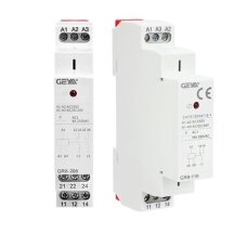 1 - 4 of 4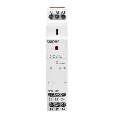
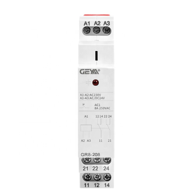
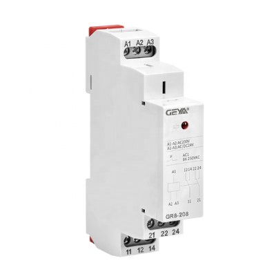 Intermediate relay | for signal amplification and load control | 2 × SPDT | 8A | AC / DC 48V | GR8-208Code: ESGR8-208Price 13.61 € VAT incl.( 11.25 € VAT excl. )
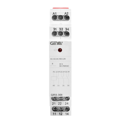 Intermediate relay | for signal amplification and load control | 3 SPDT | 8A | AC / DC 12–230V | GR8-316Code: ESGR8-3161Price 19.78 € VAT incl.( 16.35 € VAT excl. )
 Intermediate relay | for signal amplification and load control | 3 SPDT | 16 A | AC / DC 12–230V | GR8-316Code: ESGR8-3162Price 19.78 € VAT incl.( 16.35 € VAT excl. )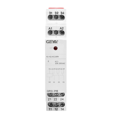
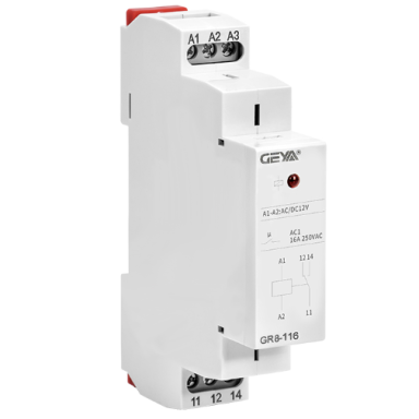 Intermediate relay | for signal amplification and load control | 3 SPDT | 16A | AC 230V | miniature | GR8-316Code: ESGR8-316Price 22.14 € VAT incl.( 18.30 € VAT excl. )


