Products catalog

Surge protectors | Protection from direct lightning current impact

  • Type 1+2 surge protective devices for the main distribution board

    If the building has a lightning protection system, the service entrance needs an SPD that can withstand partial lightning current (10/350 µs). If the house is supplied by an overhead line, we recommend T1+T2 as an extra safety margin.

    What do you need? Choose by your network and we will take you straight to the product:

    With LPS, TN-S (5 wires)
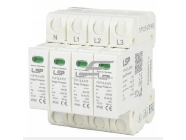
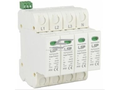
    4P (4+0), Iimp 12.5 kA per pole, Up ≤ 1.5 kV, with remote signalling contact
    FLP12.5-275/4S →
    With LPS, TN-C (4 wires, PEN)
    3P (3+0) between L and PEN, Iimp 12.5 kA per pole
    FLP12.5-275/3S →
    With LPS, TT system
    “3+1”: 3 varistors L–N at 12.5 kA each and a 50 kA N–PE spark gap
    FLP12.5-275/3S+1 →
    No LPS, overhead line
    TN-S, 4P, Iimp 5–8 kA per pole – extra margin when the house is supplied by an overhead line (our recommendation)
    FLP7-275/4S →
    Single-phase supply
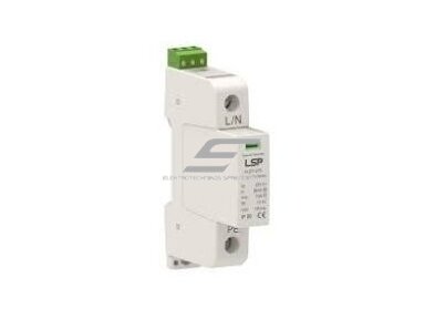
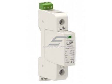
    TN-S without LPS: 2 × 1P (L–PE and N–PE), Iimp 7 kA per pole. With LPS – 2 × 12.5 kA, ask us
    FLP7-275/1S →
    Solar PV system (DC)
    DC 1000 V, T1+T2, Iimp 8 kA – when the separation distance to the LPS is not maintained
    DC T1+T2 1000 V →

    Other options: FLP12.5 4P without contact · FLP7 4P without contact · FLP7 3P (TN-C) · FLP7 spare module · A51 4P 5 kA · A51 4P 8 kA · A51 4P 12.5 kA · T2 / T3 for sub-distribution boards

    Kibirkštis Fazė
    Not sure whether you need 3P, 4P or “3+1”, or whether 7 kA is enough? Type 1+2 SPD guide – below the product list. Or ask us – we will select it based on your board diagram.
    Read more
  • К сожалению, товар не найден. Похожие товары в этой категории отображаются ниже.

    Type 1+2 SPD guide: how to select an SPD for the main distribution board

    A combined Type 1+2 SPD (class I+II / B+C) is installed in the main distribution board. It is tested with two impulse waveforms: 10/350 µs, which simulates partial direct lightning current, and 8/20 µs, which simulates an induced surge. One device therefore covers two protection stages: it diverts to earth part of the lightning current arriving through the LPS or the supply line, and it limits the voltage to a level the board equipment can withstand. Three factors determine the choice: the earthing system (3P, 4P or “3+1”), the impulse current Iimp and the connection.

    Blue – information Green – benefit to you Orange – ⚠ check this Red – ⚡ safety and mistakes

    What do you need? Quick selection

    Situation Solution Where to find it
    Building with LPS, three-phase TN-S (L1, L2, L3, N, PE) 4P (4+0), Iimp 12.5 kA per pole, Up ≤ 1.5 kV FLP12.5-275/4S · /4
    Building with LPS, three-phase TN-C (L1, L2, L3, PEN) 3P (3+0) between each phase and PEN, Iimp 12.5 kA per pole FLP12.5-275/3S
    Building with LPS, TT system (own earth electrode, RCD at the service entrance) “3+1”: 12.5 kA L–N and a 50 kA N–PE spark gap FLP12.5-275/3S+1
    No LPS, house supplied by an overhead line (TN-S after the PEN split point) 4P, Iimp 5–8 kA per pole – the safety margin we recommend FLP7-275/4S · A51 4P 8 kA
    Single-phase TN-S supply (without LPS; with LPS 2 × 12.5 kA is required – ask us) 2 × 1P: one L–PE, the other N–PE FLP7-275/1S · /1
    Solar PV system, separation distance to the LPS not maintained DC T1+T2 at the inverter (and at the PV combiner box if the DC cable is longer than ~10 m), Ucpv ≥ string Voc on the coldest day DC 1000 V, 8 kA
    The indicator shows a damaged FLP7 module Replace only the module, the base stays in place FLP7-275/0
    What you gain with the right choice
    • Partial lightning current is diverted through the SPD to PE, not through the breakers and equipment downstream.
    • One device at the service entrance replaces two protection stages – less space in the board and shorter wires.
    • The remote signalling contact (“S” models) reports a damaged module – no need to check the indicator window every week.
    • After a storm you replace only the pluggable module, not the whole SPD.

    3P, 4P or “3+1” – by earthing system

    The number of poles depends not on how many wires enter the house, but on the earthing system at the point where the SPD is installed. In Lithuania the supply is most often TN-C-S: a PEN conductor runs up to the main distribution board, where it is split into N and PE.

    Earthing system at the installation point Configuration How it is connected Our options
    TN-C (before the PEN split) 3+0 L1, L2, L3 → PEN FLP12.5-275/3S, FLP7-275/3S
    TN-S (after the PEN split) 4+0 or 3+1 4+0: L1, L2, L3, N → PE; 3+1: L → N, N → PE FLP12.5-275/4(S), FLP7-275/4(S), A51 4P, FLP12.5-275/3S+1
    TT 3+1 only (at the service entrance, upstream of the RCD) L1, L2, L3 → N, and N → PE via a spark gap FLP12.5-275/3S+1
    Single-phase TN-S 2+0 (or 1+1) L → PE and N → PE 2 × FLP7-275/1(S) or 2 × A51 1P
    Why a TT system needs “3+1”: in a TT system the earth electrode resistance is high, so if a varistor between phase and PE broke down, the fault current would be too low to blow the fuse, and a dangerous voltage would remain on the PE conductor. The spark gap between N and PE does not conduct under normal conditions, so there is no leakage current and no nuisance RCD tripping.

    Iimp: 5, 7, 8 or 12.5 kA?

    Iimp is the impulse current (10/350 µs) that the SPD can divert through one pole. When lightning strikes the LPS, the simplified assumption in EN 62305-1 is that roughly half of the current flows into the earth electrode, while the other half is shared among the conductors and services entering the building. This is where the requirement comes from.

    Situation Recommended Iimp per pole Basis
    Building with LPS, when the design does not provide a calculation ≥ 12.5 kA Default value in HD 60364-5-534
    Building with LPS, LPL I–II (explosion hazard, hospitals) Per design: LPL I – up to 25 kA, LPL II – up to ~18.75 kA per pole (when the power supply is the only service entering the building) Calculation per EN 62305-1, -4 – ask us
    No LPS, overhead line, exposed location 5–8 kA (our recommendation) Where protection is required by HD 60364-4-443, the standard calls for T2 (In ≥ 5 kA). T1+T2 is the safety margin we recommend, not a normative requirement
    No LPS, underground cable T1 is not necessary – where protection is required, T2 is sufficient T2 SPDs
    ⚠ An SPD whose data sheet or housing shows only In and Imax (8/20 µs) but no Iimp (10/350 µs) is, by its parameters, a Type 2 device. For a building with an LPS, choose an SPD with a clearly stated Iimp – all models recommended in this guide have one.

    Our series: comparison

    Series Iimp per pole (10/350) In / Imax (8/20) Up Features
    LSP FLP12.5-275 12.5 kA (3+1: N–PE 50 kA) 20 / 50 kA ≤ 1.5 kV Pluggable modules, “S” – remote signalling contact, backup fuse up to 160 A gG, terminals up to 35 mm²
    LSP FLP7-275 7 kA 20 / 50 kA ≤ 1.5 kV Pluggable modules, spare module FLP7-275/0, backup fuse up to 160 A gG
    Schelinger A51-SPD03 12.5 kA 20 / 50 kA ≤ 2.0 kV Replaceable modules, indicator; higher Up – in boards with sensitive equipment add T2 / T3
    Schelinger A51-SPD02 8 kA 20 / 50 kA ≤ 1.5 kV For houses without LPS, supplied by an overhead line
    Schelinger A51-SPD01 5 kA 20 / 50 kA ≤ 1.5 kV Budget option without LPS
    Schelinger A53 DC 8 kA – see data sheet For solar PV DC circuits up to 1000 V

    Parameters are based on LSP and Schelinger manufacturer documentation. When buying, check the data sheet of the specific model.

    Backup fuse and connection

    1. Fuse
    If the incoming fuse is larger than the manufacturer allows (FLP – 160 A gG), the SPD needs a separate fuse
    →
    2. Wires
    Not smaller than the manufacturer specifies, PE at least 16 mm² Cu; a + b ≤ 0.5 m, no loops
    →
    3. PE
    By the shortest route to the main equipotential bonding bar
    →
    4. Signal
    Connect the “S” model contact to a controller, alarm system or indicator lamp
    How to choose the fuse arrangement
    If the incoming fuse is ≤ 160 A gG, the SPD can be connected without a separate fuse, directly downstream of the incoming fuse.
    If the incoming fuse is larger than 160 A gG, a separate fuse is installed upstream of the SPD: no larger than 160 A gG and selective with the incoming fuse (typically a current ratio of ≥ 1.6, e.g. 250 A incoming – 160 A, 200 A incoming – 125 A; check the manufacturer data to confirm that the smaller fuse withstands Iimp). Only then, if the SPD fails, its own fuse will trip while the building stays powered.
    In all cases, check that the short-circuit current at the installation point does not exceed the SPD ISCCR (FLP – 25 kA).
    Terminal tightening torque for the FLP12.5 series – 4.5 Nm.

    ⚠ What to check before buying

    Kibirkštis
    Kibirkštis: “I bought a 4P, and the electrician says I have TT and needed a “3+1”. What is the difference if both have four poles?”
    What to check Why
    Earthing system at the installation point (TN-C, TN-S, TT) It determines 3+0, 4+0 or 3+1
    Whether there is an LPS and what lightning protection level it has This determines the required Iimp
    Iimp (10/350 µs) on the data sheet Without it, the SPD is a Type 2 device by its parameters
    Incoming fuse rating If it exceeds the permitted backup fuse, a separate fuse is needed
    Space in the board near the incoming supply and the PE bar Long wires add about 1 kV per metre
    Whether a remote signalling contact is needed “S” models report a damaged module remotely
    Distance to sensitive equipment More than ~10 m of cable – add T2 in the sub-distribution board or T3 at the equipment

    ✗ Most common mistakes

    Mistake Consequence
    Building with LPS, but a “T1” without a stated Iimp or with 5 kA at the service entrance The SPD may be overloaded and destroyed by the first stronger strike; protection is not ensured
    4+0 installed in a TT system instead of 3+1 Downstream of the RCD – nuisance RCD tripping; upstream of the RCD, if a varistor breaks down – dangerous voltage on the PE conductor
    4P installed in the TN-C section (before the PEN split), with N and PE terminals bridged by a jumper The N pole is short-circuited and does nothing – you overpay for an unused module, and replacement and testing become confusing. Correct: 3+0 between the phases and PEN
    SPD downstream of the incoming RCD Impulse current may trip the RCD unnecessarily or damage it. Install the incoming T1+T2 upstream of the RCD; for an SPD downstream of an RCD, the RCD must be surge-current resistant (type S), but this is not a reliable solution for partial lightning current
    No backup fuse when the incoming fuse is larger than permitted If the SPD fails, it may not be disconnected safely
    Modules from different manufacturers in one base Parameters are no longer guaranteed – replace only with a module of the same series
    ⚡ Module replaced without disconnecting the supply Risk of electric shock and arc flash
    Fazė
    ⚡ Safe installation – Fazė's tip
    A Type 1+2 SPD is installed in the main distribution board itself, where the surge has not yet reached the equipment. Some connections are upstream of the main breaker, so work only with the supply disconnected and after verifying that no voltage is present; the section upstream of the meter can only be disconnected by the network operator. Tighten the terminals to the torque specified by the manufacturer, and keep the wires short and straight. Do not work at the service entrance during a thunderstorm. Installation must be carried out by a qualified electrician.
    ☝ Elsprendimai.eu recommends

    Diagram: TT system – wrong and right

    Kibirkštis
    Kibirkštis: “I installed a T1+T2, and now the incoming RCD sometimes trips for no reason. Is the SPD faulty?”
    Fazė
    Fazė: “The SPD is fine, but it is the wrong type for this system and in the wrong place. Take a look.”
    ✗ WRONG
    ① 200 A incoming fuses, no separate fuse for the SPD
    ↓
    ② RCD, with the SPD downstream
    ↓
    ③ 4+0: each pole – a varistor to PE
    ↓
    ④ 1.2 m PE wire to a distant terminal
    ✓ RIGHT
    ① Separate SPD fuse: ≤ 160 A gG and selective with the 200 A incoming fuse (e.g. 125 A gG)
    ↓
    ② SPD upstream of the RCD
    ↓
    ③ 3+1: L–N varistors, N–PE spark gap
    ↓
    ④ a + b ≤ 0.5 m, PE directly to the main bar
    Why – explanation by diagram number
    1. ①: for the FLP series the manufacturer allows a backup fuse of up to 160 A gG. With 200 A incoming fuses, a failed SPD without its own fuse may not be disconnected safely. A separate fuse (e.g. 125 A gG – current ratio to 200 A ≥ 1.6) disconnects it selectively, and the building stays powered.
    2. ②: impulse current flowing through the RCD trips it unnecessarily or damages it. An SPD installed upstream of the RCD diverts the current before it reaches the RCD.
    3. ③: in a TT system, a varistor between phase and PE downstream of the RCD discharges current to PE during every surge, so the RCD trips unnecessarily. If such an SPD is upstream of the RCD and breaks down, a dangerous voltage remains on the PE conductor: because of the high earth electrode resistance, the fault current is too low to blow the fuse. In “3+1” the varistors are connected between L and N, and the N–PE spark gap does not conduct under normal conditions.
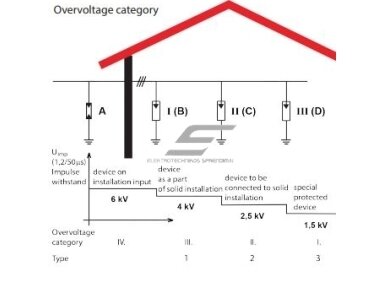
    4. ④: every metre of connecting wire adds about 1 kV to the SPD Up. With a total connecting lead length (a + b) of 1.2 m, the voltage at the terminals is ≈ 1.5 + 1.2 ≈ 2.7 kV – more than the 2.5 kV that category II equipment withstands. With ≤ 0.5 m – ≈ 2.0 kV.
    ⚠ The diagram is for guidance only. Check the SPD type, fuse and connection against the manufacturer's instructions and the design. Installation is carried out by, and is the responsibility of, a qualified electrician. UAB “Elektrotechnikos sprendimai” is not liable for improper installation or connection.

    FAQ

    Kibirkštis: What does the letter “S” in the model name mean?

    Fazė: In the FLP series, “S” stands for a remote signalling contact. If a module fails, the contact changes over, notifying a controller, alarm system or control room. Models without “S” have only a local indicator.

    Kibirkštis: Is a T1+T2 at the service entrance enough, or do I also need a T2 in the sub-distribution board?

    Fazė: If the equipment is close to the service entrance, it is often enough. If a sub-distribution board or sensitive equipment is more than ~10 m away by cable, an additional T2 is installed there, and a T3 at sensitive electronics.

    Kibirkštis: Why 12.5 kA if the design lightning current is 100 kA or more?

    Fazė: Not all of the lightning current flows through the SPD. About half is diverted by the earth electrode, and the rest is shared among several conductors and services entering the building. Each SPD pole takes only a share – so if the design does not provide a calculation, 12.5 kA per pole is used (100 kA × 50 % ÷ 4 conductors = 12.5 kA).

    Kibirkštis: I have TN-C-S. Where should the SPD go – before or after the PEN split?

    Fazė: Either is possible, only the configuration differs: before the split – 3+0 between the phases and PEN, after the split – 4+0 or 3+1. In practice it is most often installed right after the PEN split point, next to the main PE bar.

    Kibirkštis: The indicator has turned red. Do I need to replace the whole SPD?

    Fazė: No. With the supply disconnected, pull out the damaged module and insert a new one of the same series, e.g. FLP7-275/0. After a severe storm, also check the SPDs in the other boards.

    Sources: LSP catalogue “Type 1+2 AC Surge Protective Device FLP12,5 series” (2025-12); LSP FLP7-275/4S and FLP12,5-275/1S product pages; Schelinger SPD catalogue sheet (BEMKO); HD 60364-5-534 (selection and erection of SPDs); EN 61643-11 (low-voltage surge protective devices); EN 62305-1, -4 (protection against lightning). Checked 2026-10-17.

    Send us your board diagram – we will select the SPD

    Tell us the earthing system (TN-C, TN-S, TT), the incoming fuse rating and whether the building has an LPS. We will propose a Type 1+2 SPD, a fuse and T2 for sub-distribution boards – with prices.

    Get a quote →
    Read more
    Modular surge protective device T1+T2 (B+C) | 4P | Iimp 7 kA | Imax 60 kA | Uc 280 V AC | Up ≤ 1.4 kV | DIN | Elsp Group G20-B+C-7-280-4P
    Code: G20-B+C-7-280-4P

    Four-pole T1+T2 (B+C) surge protective device for the main board: Iimp 7 kA (10/350 µs) per pole, Imax 60 kA, Uc 280 V AC, Up ≤ 1.4 kV. 4+0 configuration for TN-S / TN-C-S systems, replaceable modules with status indicator, DIN rail mounting.

    Price 49.61 € VAT incl.
    ( 41.00 € VAT excl. )
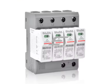
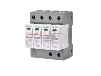
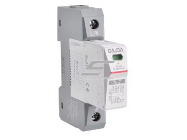
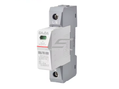
    Surge protective device Type 1+2 (B+C) | 1P | Iimp 12.5 kA | Imax 60 kA | Uc 280 V | Up ≤ 1.5 kV | GA&DA G30-B+C/280/12.5-1P
    Code: G30-B+C/280/12.5-1P

    GA&DA G30-B+C/280/12.5-1P is a modular Type 1+2 (B+C) surge protective device with plug-in modules and status indicator. Iimp 12.5 kA (10/350 µs), Imax 60 kA, Up ≤ 1.5 kV, Uc 280 V. Single pole – the scheme is built from several units.

    Price 15.73 € VAT incl.
    ( 13.00 € VAT excl. )
    Surge protective device Type 1+2 (B+C) | 1P | In 20 kA | Imax 40 kA | Uc 275 V | Up < 1.8 kV | Promfactor Baltic MOP1-BC275/20
    Code: MOP1-BC275/20

    Promfactor Baltic MOP1-BC275/20 is a single-pole surge protective device classified by the manufacturer as B+C (Type 1+2). In 20 kA, Imax 40 kA (8/20 µs), Up < 1.8 kV, Uc 275 V. DIN rail mounting in the main board.

    Price 16.90 € VAT incl.
    ( 13.97 € VAT excl. )
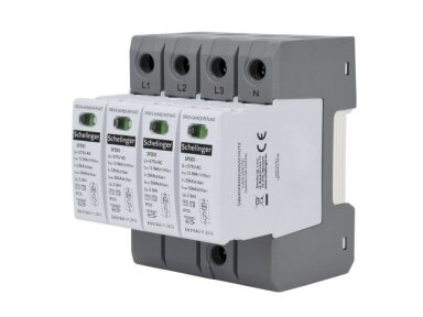
    Surge protective device Type 1+2 (B+C) | 4P | Iimp 12.5 kA (10/350) | Imax 50 kA | Up ≤ 2.0 kV | IP20 | SCHELINGER A51-SPD03-4P-B+C
    Code: A51-SPD03-4P-B+C

    SCHELINGER A51-SPD03-4P-B+C is a modular Type 1+2 (B+C) surge protective device with plug-in varistor modules. Iimp 12.5 kA (10/350 µs) per pole, In 20 kA, Imax 50 kA, Up ≤ 2.0 kV. Suitable for the incoming or main board.

    Price 54.43 € VAT incl.
    ( 44.99 € VAT excl. )
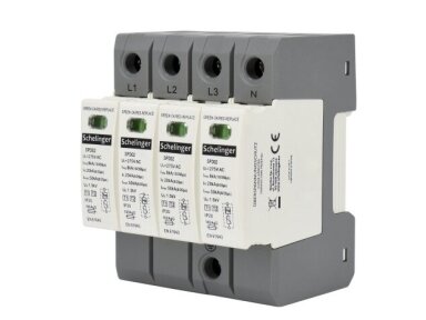
    Surge protective device Type 1+2 (B+C) | 4P | Iimp 8 kA (10/350) | Imax 50 kA | Up ≤ 1.5 kV | IP20 | SCHELINGER A51-SPD02-4P-B+C
    Code: A51-SPD02-4P-B+C

    SCHELINGER A51-SPD02-4P-B+C is a modular Type 1+2 (B+C) surge protective device with plug-in varistor modules. Iimp 8 kA (10/350 µs) per pole, In 20 kA, Imax 50 kA, Up ≤ 1.5 kV. Suitable for the incoming or main board.

    Price 39.88 € VAT incl.
    ( 32.96 € VAT excl. )
    Surge protective device Type 1+2 (B+C) | 1P | Iimp 8 kA (10/350) | Imax 50 kA | Up ≤ 1.5 kV | IP20 | SCHELINGER A51-SPD02-1P-B+C
    Code: A51-SPD02-1P-B+C

    SCHELINGER A51-SPD02-1P-B+C is a modular Type 1+2 (B+C) surge protective device with plug-in varistor modules. Iimp 8 kA (10/350 µs) per pole, In 20 kA, Imax 50 kA, Up ≤ 1.5 kV. Suitable for the incoming or main board.

    Price 9.06 € VAT incl.
    ( 7.49 € VAT excl. )
    Surge protective device Type 1+2 (B+C) | 4P | Iimp 5 kA (10/350) | Imax 50 kA | Up ≤ 1.5 kV | IP20 | SCHELINGER A51-SPD01-4P-B+C
    Code: A51-SPD01-4P-B+C

    SCHELINGER A51-SPD01-4P-B+C is a modular Type 1+2 (B+C) surge protective device with plug-in varistor modules. Iimp 5 kA (10/350 µs) per pole, In 20 kA, Imax 50 kA, Up ≤ 1.5 kV. Suitable for the incoming or main board.

    Price 29.02 € VAT incl.
    ( 23.99 € VAT excl. )
    Surge protective device Type 1+2 (B+C) | 1P | Iimp 5 kA (10/350) | Imax 50 kA | Up ≤ 1.5 kV | IP20 | SCHELINGER A51-SPD01-1P-B+C
    Code: A51-SPD01-1P-B+C

    SCHELINGER A51-SPD01-1P-B+C is a modular Type 1+2 (B+C) surge protective device with plug-in varistor modules. Iimp 5 kA (10/350 µs) per pole, In 20 kA, Imax 50 kA, Up ≤ 1.5 kV. Suitable for the incoming or main board.

    Price 7.06 € VAT incl.
    ( 5.84 € VAT excl. )
    Surge protective device Type 1+2+3 (B+C+D) | 1P | Iimp 12.5 kA | In 30 kA | Imax 50 kA | Uc 280 V | Up < 1.3 kV | PO I 1
    Code: SKU#158869360260671971

    PO I 1 is a single-pole Type 1+2+3 (B+C+D) surge protective device: incomer and fine protection stages in one 2.5-module housing. Iimp 12.5 kA (10/350 µs), In 30 kA, Imax 50 kA, Up < 1.3 kV, Uc 280 V.

    Price 34.09 € VAT incl.
    ( 28.18 € VAT excl. )
    Surge protective device Type 1+2 (B+C) | 4P TN-S | Iimp 7 kA | Imax 50 kA | Up ≤ 1.5 kV | LSP FLP7-275/4
    Code: FLP7-275/4

    LSP FLP7-275/4 is a combined Type 1+2 (B+C) surge protective device for the main distribution board. It handles a partial lightning current of 7 kA (10/350 µs) per pole and limits the overvoltage to ≤ 1.5 kV. Configuration: 4P (4+0) – for TN-S: L1, L2, L3, N → PE.

    Price 69.45 € VAT incl.
    ( 57.40 € VAT excl. )
    Surge protective device Type 1+2 (B+C) | 4P TN-S | Iimp 7 kA | Imax 50 kA | Up ≤ 1.5 kV | with remote contact | LSP FLP7-275/4S
    Code: FLP7-275/4S

    LSP FLP7-275/4S is a combined Type 1+2 (B+C) surge protective device for the main distribution board. It handles a partial lightning current of 7 kA (10/350 µs) per pole and limits the overvoltage to ≤ 1.5 kV. Configuration: 4P (4+0) – for TN-S: L1, L2, L3, N → PE.

    Price 72.84 € VAT incl.
    ( 60.20 € VAT excl. )
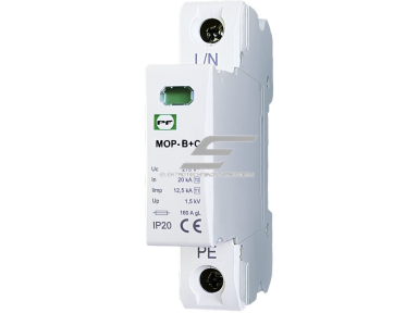
    Surge protective device Type 1+2 (B+C) | 4P | In 20 kA | Imax 40 kA | Uc 275 V | Up < 1.5 kV | Promfactor Baltic MOP4-BC275/20
    Code: MOP4-BC275/20

    Promfactor Baltic MOP4-BC275/20 is a four-pole surge protective device classified by the manufacturer as B+C (Type 1+2). In 20 kA, Imax 40 kA (8/20 µs), Up < 1.5 kV, Uc 275 V. DIN rail mounting in the main board.

    Price 67.61 € VAT incl.
    ( 55.88 € VAT excl. )
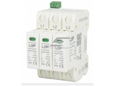
    Surge protective device Type 1+2 (B+C) | 3P TN-C | Iimp 12.5 kA | Imax 50 kA | Up ≤ 1.5 kV | with remote contact | LSP FLP12.5-275/3S
    Code: FLP12.5-275/3S

    LSP FLP12.5-275/3S is a combined Type 1+2 (B+C) surge protective device for the main distribution board. It handles a partial lightning current of 12.5 kA (10/350 µs) per pole and limits the overvoltage to ≤ 1.5 kV. Configuration: 3P (3+0) – for TN-C: L1, L2, L3 → PEN.

    Price 96.56 € VAT incl.
    ( 79.80 € VAT excl. )
    Surge protective device Type 1+2 (B+C) | 3+1 TT/TN-S | Iimp 12.5 kA | Imax 50 kA | Up ≤ 1.5 kV | with remote contact | LSP FLP12.5-275/3S+1
    Code: FLP12.5-275/3S+1

    LSP FLP12.5-275/3S+1 is a combined Type 1+2 (B+C) surge protective device for the main distribution board. It handles a partial lightning current of 12.5 kA (10/350 µs) per pole and limits the overvoltage to ≤ 1.5 kV. Configuration: 3P+N (3+1) – for TT and TN-S: L1, L2, L3 → N varistors, N → PE spark gap (Iimp 50 kA).

    Price 147.38 € VAT incl.
    ( 121.80 € VAT excl. )
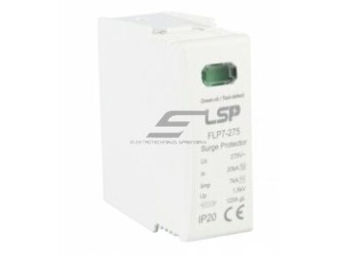
    Replacement SPD module Type 1+2 | Iimp 7 kA | Imax 50 kA | Uc 275 V | LSP FLP7-275/0
    Code: FLP7-275/0

    LSP FLP7-275/0 is a replacement Type 1+2 plug-in module for FLP7-275 series bases. When the indicator turns red, pull out the module and insert a new one – no rewiring, the base stays.

    Price 15.25 € VAT incl.
    ( 12.60 € VAT excl. )
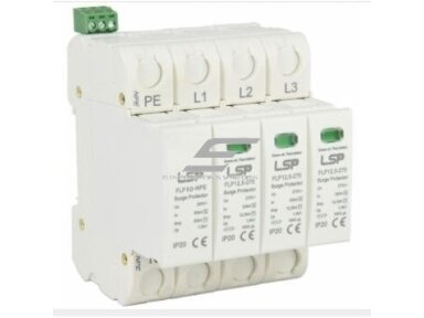
    Surge protective device Type 1+2 (B+C) | 4P TN-S | Iimp 12.5 kA | Imax 50 kA | Up ≤ 1.5 kV | LSP FLP12.5-275/4
    Code: FLP12.5-275/4

    LSP FLP12.5-275/4 is a combined Type 1+2 (B+C) surge protective device for the main distribution board. It handles a partial lightning current of 12.5 kA (10/350 µs) per pole and limits the overvoltage to ≤ 1.5 kV. Configuration: 4P (4+0) – for TN-S: L1, L2, L3, N → PE.

    Price 120.27 € VAT incl.
    ( 99.40 € VAT excl. )
    Surge protective device Type 1+2 (B+C) | 4P TN-S | Iimp 12.5 kA | Imax 50 kA | Up ≤ 1.5 kV | with remote contact | LSP FLP12.5-275/4S
    Code: FLP12.5-275/4S

    LSP FLP12.5-275/4S is a combined Type 1+2 (B+C) surge protective device for the main distribution board. It handles a partial lightning current of 12.5 kA (10/350 µs) per pole and limits the overvoltage to ≤ 1.5 kV. Configuration: 4P (4+0) – for TN-S: L1, L2, L3, N → PE.

    Price 123.66 € VAT incl.
    ( 102.20 € VAT excl. )
    Surge protective device Type 1+2 (B+C) | 1P | Iimp 7 kA | Imax 50 kA | Up ≤ 1.5 kV | LSP FLP7-275/1
    Code: FLP7-275/1

    LSP FLP7-275/1 is a combined Type 1+2 (B+C) surge protective device for the main distribution board. It handles a partial lightning current of 7 kA (10/350 µs) per pole and limits the overvoltage to ≤ 1.5 kV. Configuration: 1P – single pole; build the scheme from several units (e.g. L–PE and N–PE for single-phase TN-S).

    Price 17.36 € VAT incl.
    ( 14.35 € VAT excl. )
    Surge protective device Type 1+2 (B+C) | 1P | Iimp 7 kA | Imax 50 kA | Up ≤ 1.5 kV | with remote contact | LSP FLP7-275/1S
    Code: FLP7-275/1S

    LSP FLP7-275/1S is a combined Type 1+2 (B+C) surge protective device for the main distribution board. It handles a partial lightning current of 7 kA (10/350 µs) per pole and limits the overvoltage to ≤ 1.5 kV. Configuration: 1P – single pole; build the scheme from several units (e.g. L–PE and N–PE for single-phase TN-S).

    Price 19.06 € VAT incl.
    ( 15.75 € VAT excl. )
    Surge protective device Type 1+2 (B+C) | 3P TN-C | Iimp 7 kA | Imax 50 kA | Up ≤ 1.5 kV | with remote contact | LSP FLP7-275/3S
    Code: FLP7-275/3S

    LSP FLP7-275/3S is a combined Type 1+2 (B+C) surge protective device for the main distribution board. It handles a partial lightning current of 7 kA (10/350 µs) per pole and limits the overvoltage to ≤ 1.5 kV. Configuration: 3P (3+0) – for TN-C: L1, L2, L3 → PEN.

    Price 55.90 € VAT incl.
    ( 46.20 € VAT excl. )
  • privacy policy

    Information