


Photo relays | twilight switches | mounted in electrical distribution boxes | panels
-
Photo relay guide: how to choose, where to mount the sensor and how to connect LED
Here you will find a quick selection by situation, a comparison matrix of all relays in the group, an illuminance (lx) scale, LED load calculation, the most common mistakes with a diagram and answers to practical questions. Exact parameters are given in each product description.
Colour key: ■ information · ■ benefit, solution · ■ ⚠ check · ■ ⚡ safety, mistakes
Contents: What do you need? · Modular or wall-mounted · Timer and night mode · Selection matrix · How many lux · LED load · What to check · Mistakes · Diagram · FAQ · SourcesWhat do you need? Quick selection
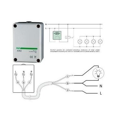
Situation Solution Where to look Simple yard, entrance or terrace lighting, no room in the panel Wall-mounted twilight switch with built-in sensor – wired directly into the lighting circuit F&F AWZ, Night-Matic 2000, ES-G02 Lighting is controlled from the panel, the sensor can be placed outdoors Modular DIN relay with an external sensor (IP54–IP65) on the wall VEXEN TWR1, F&F AZ 112, GTV CZ-1 Lights must go off at night and come on again early in the morning Relay with a daily programme or night economy mode VEXEN DTWR972, Finder 11.91, Night-Matic 3000, Night-Matic 5000-3 A few hours after dusk are enough, without setting a clock Wall-mounted relay with an on-time knob GTV CZ-2, WYL-CR-M2-SZ-01 12 / 24 V system: off-grid, solar or low-voltage lighting Universal supply relay 12–240 V AC/DC SOU-1/UNI High load, many LED floodlights 25 A relay or photo relay + modular contactor Promfactor FRS21, 65593, kontaktoriai Control by daylight: blinds, awnings, daytime signage Wide-range relay – up to 10.000 or 50.000 lx VEXEN VSOU-1, Eti SOU-1, VEXEN TWR923 Wide supply range for an outdoor relay Twilight switch with built-in sensor, 24–264 V AC ES-TS01 The external sensor of a Finder relay has failed Spare sensor for Finder 11.31, 11.41, 11.42, 11.91 relays Finder 011.02 Light only when it is needed – without resetting clocks
A timer does not know that today is overcast, and a manual switch depends on someone remembering. A photo relay measures real illuminance: lighting switches on at dusk and off at dawn all year round, and with a daily programme or night mode it also goes off when nobody is around.
- Yard, paths, driveway: wall-mounted relay or modular relay with the sensor on a north wall.
- Signs and shop windows: relay with night switch-off – on in the evening and morning, not all night.
- Streets and car parks: modular relay in the panel + contactor for the LED floodlight group.
- Blinds, awnings, signage: wide-range relay that also responds to bright daylight.
Quick selection by parameters – selection matrix · how to connect – diagram
Modular or wall-mounted photo relay?
Both do the same job; the difference is where the relay sits and where the sensor sits. This determines installation, load and how easy it is to change something later.
■ Modular DIN relay with external sensor
- The relay sits in a dry panel on a DIN rail (1–2 modules), only the IP54–IP65 sensor is outdoors.
- The sensor can be placed where it sees daylight: cable up to 50 m (AZ-112 – up to 10 m).
- Easy to combine with a contactor, timer and circuit breakers – everything in one place.
- Widest choice: from 1–100 lx to 1–50.000 lx, with daily programme, 25 A output, 12–240 V AC/DC supply.
- Needs space in the panel and a separate cable to the sensor.
■ Wall-mounted relay with built-in sensor
- Relay and sensor in one housing (IP44–IP65) – mounted on the wall, wired directly into the lighting circuit.
- Simple: e.g. GTV CZ-2 is connected with three wires – line, neutral and output to the load.
- Suits a single yard, entrance or terrace where there is no panel or no wish to run an extra cable.
- The location must suit both: the sensor must see daylight, the housing must be protected from water.
- Load is limited by the built-in relay: 6–25 A, LED limits – as stated by the manufacturer.
Timer and night mode: when a photo relay is enough and when it is not
A simple photo relay keeps the lighting on all night. For signs, car parks and yards where nobody walks at night, choose a relay that switches the light off at night and, if needed, on again early in the morning:
Dusk – light ON→Night window (e.g. 23:00) – OFF→Early morning (e.g. 05:30), still dark – ON→Daylight – OFF- Daily programme with a clock: VEXEN DTWR972 (Lux / Night OFF / Night ON, 2 memory slots) and Finder 11.91 (off time or off and on times, automatic summer / winter time).
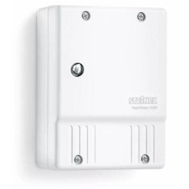
- Night economy mode without programming: Night-Matic 3000 and Night-Matic 5000-3 – the light goes off at night, in the morning ON or OFF is selectable.
- Limited on-time: GTV CZ-2 (1–9 h or until dawn) and WYL-CR-M2-SZ-01 (1–8 h or until dawn).
- External blocking: VEXEN VSOU-1, Eti SOU-1 and SOU-1/UNI have a control input S – a timer or another control contact is connected to it.
Selection matrix: all photo relays in the group
The table lists the main parameters from manufacturers' data. “–” means the manufacturer does not state the parameter or the function is not available. LED load is given only where the manufacturer states it.
Product Type Range Output / load Timer / night mode Sensor IP Modular (DIN rail) and sensor VEXEN TWR1 modular, 1 mod. 1–100 lx 1NO, 16 A AC1 – IP65 VEXEN TWR923 modular, 1 mod. 1–1000 / 10–10,000 lx 1NO, 16 A AC1 – IP65 VEXEN VSOU-1 modular, 1 mod. 1–100 / 100–50,000 lx 1CO, 16 A AC1 S input (external control) IP56 Eti SOU-1 modular, 1 mod. 1–100 / 100–50,000 lx 1CO, 16 A AC1 S input (external control) IP65 SOU-1/UNI modular, 1 mod. 1–100 / 100–50,000 lx 1CO, 16 A AC1; supply 12–240 V AC/DC S input (external control) – VEXEN DTWR972 modular, 2 mod. 1–1000 lx 1CO, 16 A; LED 200 W daily programme, Night OFF / ON IP54 Finder 11.91 modular, 2 mod. 2–150 lx 1CO, 16 A AC1; LED 400 W daily programme (OFF / ON times) IP54 F&F AZ 112 modular, 1 mod. 2–1000 lx 1NO, 16 A AC1; LED 250 W – IP65 Promfactor FRS21 modular, 2 mod. 2–100 lx 1CO, 25 A – – GTV CZ-1 modular, 2 mod. 2–100 lx 20 A; 4800 W – IP65 Finder 011.02 external sensor – Finder 11.31 / 11.41 / 11.42 / 11.91 – IP54 Wall-mounted and outdoor with built-in sensor F&F AWZ wall-mounted 2–1000 lx 1NO, 16 A; LED 250 W – IP65 Night-Matic 2000 wall-mounted 2–30 lx 1000 W (incandescent); LED: 4 pcs × max. 58 W – IP54 Night-Matic 3000 wall-mounted 0.5–10 lx 1000 W (incandescent); LED: up to 64 W, ≤ 4 pcs night economy mode IP54 Night-Matic 5000-3 wall-mounted 2–1000 lx 2000 W (incandescent); LED: up to 600 W, ≤ 8 pcs night economy mode IP54 GTV CZ-2 wall-mounted 3–200 lx 6 A / 1500 W 1–9 h or until dawn IP44 WYL-CR-M2-SZ-01 wall-mounted 3–500 lx 1200 W 1–8 h or until dawn IP44 HOROZ 0890010001 wall-mounted 5–15 lx 6 A / 1000 W – IP44 ES-G02 wall-mounted ON 10–100 / OFF 40–250 lx 10 A – IP44 ES-G03 outdoor, wall ON ~10 / OFF ~40 lx (fixed) 10 A – IP65 65593 wall-mounted ON 10–50 / OFF 50–100 lx 25 A – IP44 ES-TS01 outdoor, wall not stated 1NO, 16 A AC1; supply 24–264 V AC – – Thresholds marked “ON / OFF” are separate switch-on and switch-off thresholds. For wall-mounted relays the IP of the whole housing is given. Always check the specific product description before buying.
How many lux? Illuminance scale and recommended thresholds
Lux (lx) is the unit of illuminance. The eye perceives it logarithmically, so the difference between 1 and 10 lx looks similar to that between 1000 and 10,000 lx. Indicative levels:
Which threshold to set
Yard, paths, street, driveway 5–20 lx Switches on when it is really dark – no wasted hours. Shop windows, signs, advertising 30–80 lx Switches on earlier, while it is still fairly light – the sign is visible at dusk. Control by daylight (blinds, awnings) > 1000 lx Needs a relay with a 10,000 or 50,000 lx range. Range covered by each relay (logarithmic scale 0.1–100.000 lx)
0.1110100100010,000100,000lxGreen band – yard (5–20 lx), orange – shop windows (30–80 lx).
In practice: start at ~10 lx, watch for a few evenings and adjust. Sensor tolerance can be large (e.g. VEXEN TWR1 – ±35 %), so the knob scale is a guide, not a measuring instrument.
LED load: why a 16 A relay cannot handle 16 A of LED floodlights
The rated current of a relay (e.g. 16 A AC1) applies to an active, resistive load. LED drivers have a capacitor at the input which, at switch-on, charges with a short but very high current pulse. The pulses of several drivers add up, the relay contact arcs, wears and can weld – then the lighting no longer switches off. That is why manufacturers state the LED load separately, and it is much lower.
How to calculate: add up the power of all luminaires and compare it with the LED load stated by the manufacturer (not the AC1 value). E.g. 6 LED floodlights × 50 W = 300 W. With AZ-112 (LED 250 W) – exceeded, a contactor is needed. With Finder 11.91 (LED 400 W) – it fits, but if you plan to expand or the floodlight drivers have a high inrush current, fit a contactor straight away. Remember: 16 A × 230 V = 3680 W applies only to an AC1 load – the AZ-112 LED limit of 250 W is only ~1.1 A. When the limit is exceeded, the photo relay switches only the coil of a modular contactor, and the contactor is selected by the lamp / LED load stated by its manufacturer.
Product Manufacturer's LED limit Other data VEXEN DTWR972 LED 230 V (> 5 W): 200 W inrush current up to 50 A, 20 ms F&F AZ 112 LED 250 W incandescent lamps 2000 W F&F AWZ LED 250 W incandescent lamps 4000 W Finder 11.91 LED 400 W inrush peak 120 A, 5 ms Night-Matic 2000 4 pcs × max. 58 W (C ≤ 88 µF) incandescent lamps 1000 W Night-Matic 3000 up to 64 W, max. 4 pcs capacitive load up to 88 µF Night-Matic 5000-3 < 2 W – 100 W; > 2 W – 300 W; > 8 W – 600 W; ≤ 8 pcs capacitive load up to 176 µF Eti SOU-1 LED limit not stated 16 A AC1, inrush current 30 A (< 3 s) When the manufacturer does not state an LED limit, always use a contactor for larger LED groups.
⚠ What to check before buying
 KibirkštisBefore I buy a photo relay I always check these things – otherwise I end up driving to the site twice.
What to check Why it matters Where the relay will be In the panel – modular DIN with external sensor; on the wall – wall-mounted with built-in sensor and suitable IP. Sensitivity range (lx) For a yard up to 100 lx is enough; for shop windows – at least up to 100 lx; for daylight control – 10.000–50.000 lx. LED / lamp load Look at the manufacturer's LED limit, not 16 A AC1. If exceeded – a contactor. Output: NO or CO 1NO – simple switching. 1CO (changeover) also allows inverse logic or a signal. Timer / night mode Do the lights need to go off at night? If so – daily programme, night mode or S input. Sensor IP and cable length Outdoors – IP54 or higher. Cable up to 50 m (AZ-112 – up to 10 m). Supply voltage 230 V AC, 110–240 V AC, 12–240 V AC/DC or 24–264 V AC – to suit your system. Operating temperature E.g. FRS21 – −5…+40 °C (heated panel only), TWR923 – −35…+75 °C. ✗ Most common mistakes
Mistake Consequence The sensor is reached by light from the controlled luminaires The relay switches itself off and on again – lighting flickers in the evening and morning. The sensor faces south or the road Sun or car headlights switch the lighting off at the wrong time. Threshold too high (e.g. 100 lx for a yard) Lighting comes on while it is still light and burns for nothing. An LED floodlight group directly on the relay, exceeding the LED limit The contact welds – the light no longer switches off and the relay must be replaced. A modular (IP20) relay in an outdoor box or damp location Moisture, condensation, corrosion – the relay fails. Cable entered into a wall-mounted relay from above Water runs down the cable into the housing. Finder 011.02 connected to old 11.01 or 11.71 relays Not compatible – the relay will not work. The sensor line run as low-current wire next to 230 V cables ⚡ On some relays the sensor circuit is not isolated from the mains – the wires may carry a dangerous voltage. How the main mistakes look in practice – see the diagram.

⚡ Safe installation – Fazė's advice
- Before installation, isolate the circuit and verify that it is dead.
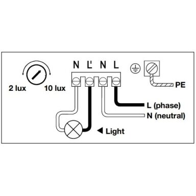
- Protect the lighting circuit with a circuit breaker sized for the cable; where the manufacturer states a value, follow it (e.g. Steinel NightMatic 2000 / 3000 – 10 A).
- Run the sensor cable as a 230 V circuit: outdoors – H05RR-F or better, indoors – H05VV-F or better (DTWR972 instructions).
- A modular relay goes only in a dry panel (IP20); outdoors install only the sensor or a wall-mounted relay with a suitable IP, cable from below.
- Connect LED groups exceeding the manufacturer's LED limit via a modular contactor.
- Connection to the 230 V mains must be carried out by a qualified electrician.
☝ Elsprendimai.eu recommends: complete the photo relay with modular contactors for LED floodlight groups, circuit breakers for lighting and control circuits, time relays for more complex logic, staircase lighting timers for stairwells and corridors, motion sensors for paths and entrances and LED floodlights.Diagram: connecting a photo relay – wrong and correct
Diagram. Photo relay, sensor and LED floodlight group. The most common photo relay problems are a welded contact, flickering lighting and a badly routed sensor line. Left – how it is often done, right – how it should be. The numbers in the diagram match the explanations below it.
KibirkštisI hung six LED floodlights on a 16 A photo relay – after a month the light no longer switches off, and before that it flickered in the evenings. What is going on?
FazėTwo things at once. The LED inrush current welded the relay contact – for such a group the relay must switch a contactor coil. And it flickered because the sensor sees your floodlights. Move it to a north wall, higher up and out of the light zone.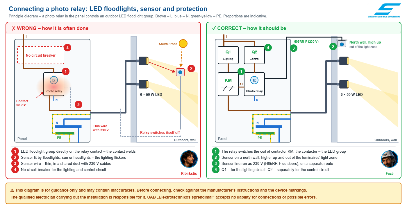 ☝ Click the diagram to open the enlarged version.⚠ This diagram is for guidance only and may contain inaccuracies. Before connecting, check against the manufacturer's instructions and the device markings.
The qualified electrician carrying out the installation is responsible for it. UAB „Elektrotechnikos sprendimai“ accepts no liability for connections or possible errors.Why – explanation by the numbers in the diagram
1LED load and the relay contact
✗ LED floodlight group directly on the relay contact → ✓ The relay switches the contactor coil, the contactor switches the LED group
Why: 16 A AC1 means an active (resistive) load – utilisation category AC-1 under IEC 60947-4-1. The input capacitor of an LED driver causes a current pulse at switch-on that can reach hundreds of times the rated current but lasts less than 1 ms (Schneider Electric, Electrical Installation Guide). The pulses of several drivers add up, the contact arcs and can weld. That is why manufacturers limit the LED load separately: AZ-112 – 250 W, DTWR972 – 200 W (inrush current up to 50 A, 20 ms), Finder 11.91 – 400 W, although all have a 16 A contact. A contactor coil is a small load for the relay, and the contactor itself is selected by the lamp / LED load stated by its manufacturer.
2Sensor position
✗ The sensor is lit by a floodlight, faces south or the road → ✓ North wall, higher up and outside the luminaires' light zone
Why: A photo relay works in a closed loop: the sensor sees not only daylight but also the light of the luminaires it controls. If a floodlight that has come on lights the sensor above the switch-off threshold, the relay switches the light off; it gets dark – it switches on again. Hysteresis and delay (e.g. TWR1 – about 2 min, AZ-112 – about 10 / 20 s) only slow the flickering down but do not remove it. The Finder datasheet also states that the luminaires' light must not influence the sensor. On a north wall the sensor is not reached by direct sun or car headlights, so it measures the overall ambient illuminance.
3Sensor cable
✗ Thin low-current wire in a shared duct with 230 V cables → ✓ The sensor line is run as 230 V, on a separate route
Why: Not every photo relay has its sensor circuit isolated from the mains: Finder 11.91 has 2000 V AC insulation between supply and sensor, while DTWR972 (Hugo Müller paladin 972) has no galvanic isolation – the sensor wires may be at mains potential. Under IEC 60364-5-52 (528.1), circuits of different voltage bands may share a duct or cable only if every conductor is insulated for the highest voltage present. So run the sensor line as 230 V: outdoors with H05RR-F or better, indoors with H05VV-F or better, up to 50 m (AZ-112 – up to 10 m). A separate route away from power cables also reduces the risk of induced interference.
4Protection
✗ Relay and LED group without their own circuit breaker → ✓ A breaker sized for the cable for the lighting circuit, a separate one for the control circuit
Why: A circuit breaker protects the cable against overload and short circuit, so it is selected by the cable cross-section and installation method (IEC 60364-4-43). Without its own protection, a short circuit in a luminaire or the sensor line can damage the relay and thin control wires. Where the manufacturer states a specific value, follow it: the Steinel NightMatic 2000 and 3000 data specify a 10 A circuit breaker. A separate control circuit breaker allows the relay and contactor to be serviced safely without switching off the whole panel.
Frequently asked questions
Asking is Kibirkštis – a young, curious electrician who dares to ask what others do not. Answering is Fazė – an experienced engineer.
KibirkštisHow many lux should I set for a yard?
FazėUsually 5–20 lx is enough – the lighting comes on when it is really dark. For shop windows and signs, 30–80 lx so that it comes on earlier. Start at ~10 lx, watch for a few evenings and adjust: the knob scale is indicative, sensor tolerance can be ±35 %.
KibirkštisModular or wall-mounted – which one?
FazėIf the lighting goes through the panel and you can place the sensor in a good spot – a modular DIN relay with an external sensor: easy to combine with a contactor and timer. If it is a single yard or entrance without a panel – a wall-mounted relay with a built-in sensor, wired directly into the lighting circuit.
KibirkštisWhy does the lighting flicker in the evening?
FazėAlmost always the sensor sees its own luminaires: the light comes on, lights the sensor, the relay switches it off – and round it goes. Move the sensor out of the light zone, ideally onto a north wall, and check that the threshold is not set too high (diagram, item 2).
KibirkštisCan LED luminaires be connected directly to a photo relay?
FazėYes, as long as the manufacturer's LED limit is not exceeded – e.g. AZ-112 and AWZ – 250 W, Finder 11.91 – 400 W, NightMatic 2000 – 4 luminaires. For a larger group or when no limit is stated – the relay switches the coil of a modular contactor.
KibirkštisHow do I make the light go off at night?
FazėChoose a relay with a daily programme – VEXEN DTWR972 or Finder 11.91, or a wall-mounted one with night mode – Night-Matic 3000, Night-Matic 5000-3. If you only need a few hours after dusk – GTV CZ-2 or WYL-CR-M2-SZ-01 with an on-time knob.
KibirkštisDoes a photo relay replace a motion sensor?
FazėNo – a photo relay responds to light, not to people. A common combination: the photo relay enables the lighting only in the dark, and a motion sensor switches it on when someone passes. Many motion sensors also have their own light threshold setting.
KibirkštisIs there a photo relay for a 12 V or 24 V system?
FazėYes – SOU-1/UNI is supplied at 12–240 V AC/DC. Its 1CO contact switches up to 250 V AC / 24 V DC; for a DC load the manufacturer states up to 384 W. For solar and off-grid systems this is the simplest solution.
KibirkštisDo you help select a relay for a project?
FazėYes. Send us the list of luminaires, their power and the required operating logic – we will select the relay, contactor and protection and prepare a quotation. Contact us.Sources
Manufacturer data and standards used in this guide. Checked 2026-10-07.
- Finder – series 11 twilight switches and sensor 011.02, datasheet S11EN
- VEXEN TWR1 – manufacturer specification
- Steinel NightMatic 2000 – manufacturer datasheet
- F&F AZ-112 – manufacturer datasheet
- Hugo Müller paladin 972,413 easy (VEXEN DTWR972) – technical data
- Schneider Electric, Electrical Installation Guide – LED lighting constraints and recommendations (inrush current)
- Examples of illuminance levels – Lux (Wikipedia)
- IEC 60364-5-52, 528.1 – circuits of different voltage bands in a common installation (Voltimum summary)
- EVS-HD 60364-4-43:2010 – protection against overcurrent
- IEC 60947-4-1 utilisation categories (AC-1, AC-5a, AC-5b) – Utilization categories (Wikipedia)
Photo relay, contactor and protection – in one order
Modular and wall-mounted photo relays, spare sensors, contactors and circuit breakers – all in one place. Send us the list of luminaires and the required operating logic: we will select compatible components and prepare a quotation. The model you need is not in the catalogue? Some products are supplied to order.
Get a quotation 1 - 16 of 22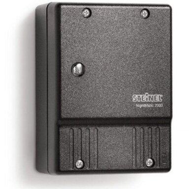

 Price 29.00 € VAT incl.( 23.97 € VAT excl. )
 Price 33.41 € VAT incl.( 27.61 € VAT excl. )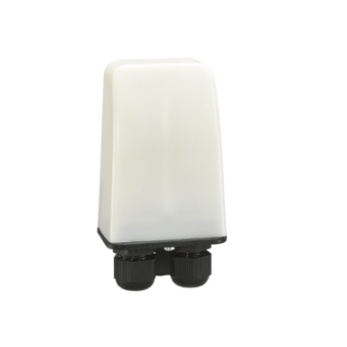
 Outdoor twilight switch | with built-in photocell | 16 A | 24–264 V AC | 1NO | Elsp Group | ES-TS01Code: ES-TS01Price 14.30 € VAT incl.( 11.82 € VAT excl. )
 Price 42.35 € VAT incl.( 35.00 € VAT excl. )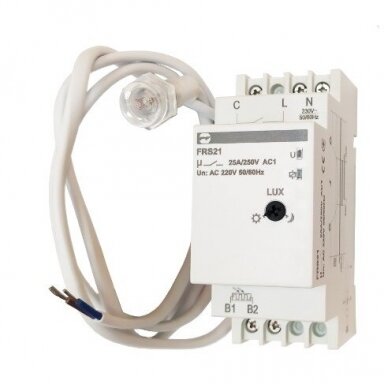
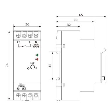 Modular photo relay | twilight switch with external sensor | 25 A | 230 V AC | 2–100 lx | 1CO | DIN | Promfactor | FRS21Code: PF-FRS21Price 16.94 € VAT incl.( 14.00 € VAT excl. )
 Price 65.88 € VAT incl.( 54.45 € VAT excl. )
 Price 48.16 € VAT incl.( 39.80 € VAT excl. )
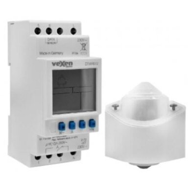 Price 110.74 € VAT incl.( 91.52 € VAT excl. )
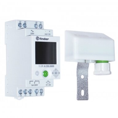 Modular photo relay | twilight switch with timer and external sensor | 16 A | 230 V AC | 2–150 lx | 1CO | IP54 sensor | DIN | Finder | 11.91.8.230.0000Code: 11.91.8.230Price 76.00 € VAT incl.( 62.81 € VAT excl. )
 Price 44.94 € VAT incl.( 37.14 € VAT excl. )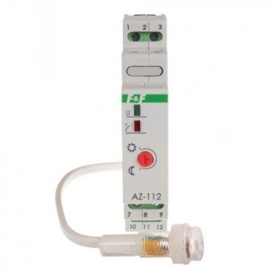
 Price 19.59 € VAT incl.( 16.19 € VAT excl. )
 Photo relay with built-in sensor | twilight switch | 25 A | 220–240 V AC | 10–100 lx | IP44 | 65593Code: 65593Price 4.72 € VAT incl.( 3.90 € VAT excl. )
 Price 7.11 € VAT incl.( 5.88 € VAT excl. )
 Photo relay with built-in sensor | wall-mounted | 10 A | 220–240 V AC | 10–250 lx | IP44 | Elsp Group | ES-G02Code: ES-G02Price 3.39 € VAT incl.( 2.80 € VAT excl. )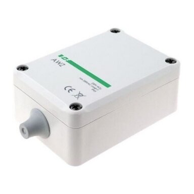
 Price 14.00 € VAT incl.( 11.57 € VAT excl. )
 Price 13.30 € VAT incl.( 10.99 € VAT excl. )


