


Differential pressure relays and transducers
-
Differential pressure guide: from a filter signal to smart control
Here you will find a quick selection by application, a comparison of simple and smart solutions, range selection, a wiring diagram with explanations, the most common mistakes and answers to key questions.
Colour key: ■ information · ■ benefit, solution · ■ ⚠ check · ■ ⚡ safety, mistakes
Contents: What do you need? · How it works · Simple or smart · Range · Signals and power supply · Diagram · What to check · Mistakes · FAQ · SourcesWhat do you need? Quick selection
Situation Solution Where to look A signal that the ventilation filter needs replacing Mechanical Δp switch, setpoint based on the filter manufacturer’s final pressure drop PSW-500, PSW-500, Δp switches Verify that the fan is actually producing airflow Δp switch measuring the pressure difference before and after the fan (fan proving) – low range, e.g. 20–200 Pa DPR-200K, ESLF32 See the filter condition at a glance, without power Analogue differential pressure gauge next to the filter ESLFB pressure gauges Accurate Δp to the building management system (BMS) Transmitter with 0–10 V / 0–20 mA / PWM output and Modbus RTU HPS-G-1K0, DPS with display Two measurements in one device (e.g. supply and extract filters) Dual differential pressure transmitter – two channels, one housing HPD-G-1K0 Maintain constant pressure in a duct or room PI controller – adjusts the fan speed or damper position by itself HPSPG (for fans), HPSAG (for dampers) Cleanroom, laboratory, pressure cascade between rooms Low-range transmitter −125…+125 Pa – shows both overpressure and negative pressure HPS-G-LP Two operating modes (e.g. day / night) with different pressure setpoints Controller with 2 setpoints – mode switched by an external contact or via Modbus SPS2G-2K0 Water, air or compressor pressure in bar Automatic pressure switch with adjustable cut-in pressure and differential ESLF55 switches, ceramic sensor Air velocity or airflow measurement in a duct Pitot tube + differential pressure transmitter Pitot kit, connection kit Replace the filter when it is needed – not “by the calendar”
A clogged filter increases fan energy consumption and reduces the airflow to the rooms, while a filter replaced too early is money thrown away. An inexpensive Δp switch or transmitter shows exactly when to replace it. We stock the whole chain – switches, transmitters, controllers, pressure gauges and connection kits. Send us the unit description – we will select a solution.
How it works: from two pressures to an action
The device has two ports: “+” (P1) for the higher pressure and “−” (P2) for the lower pressure. It does not measure the pressure itself but the difference Δp = P1 − P2 in pascals (Pa). 100 Pa = 1 mbar = 0.001 bar – a very low pressure, so even small details of the tube connections matter.
P1 / P2
upstream and downstream of the filter→Δp
difference, Pa→Switch / transmitter
contact or 0–10 V, Modbus→Controller
alarm, BMS, PI control→Action
replace filter, speed, damperSimple or smart? Four levels – from a pressure gauge to PI control
The same Δp can be used in very different ways. Choose the level according to what you need: just see it, get a signal, measure accurately or control automatically.
1 · See
Analogue pressure gauge
Shows Δp without power or wiring. Maintenance staff can see at once how dirty the filter is.
Where to use: Simple ventilation units, periodic inspection, additional visual check next to a switch or transmitter.
Products: ESLFB pressure gauges
2 · Get a signal
Mechanical Δp switch (SPDT)
Changeover contact (COM / NO / NC) switches when Δp reaches the setpoint. No power supply needed – simple and reliable.
Where to use: Dirty filter alarm, fan proving, protection against switching on the heater without airflow, frost/icing signal for a heater or heat recovery unit.
3 · Measure accurately
Transmitter 0–10 V / 0–20 mA / PWM + Modbus RTU
Continuous Δp value for a controller or BMS. It can be displayed and logged, several alarm thresholds can be set and filter replacement can be planned in advance.
Where to use: Building automation, several ventilation units in one system, cleanrooms (±125 Pa), airflow measurement with a Pitot tube.
Products: HPS, DPS with display, HPD dual
4 · Control automatically
PI controller for a fan or damper
Measures Δp and adjusts the fan speed or damper position by itself to keep the pressure at the setpoint. A controller with 2 setpoints lets you switch between two modes.
Where to use: Constant duct pressure (VAV systems), room overpressure / negative pressure, kitchen or workshop extraction, energy savings by reducing speed.
Simple solution (switch, pressure gauge) Smart solution (transmitter, PI controller) What you get Yes / no signal or a reading on a scale Accurate value, history, several thresholds, automatic control Power supply Not required (switch contact – up to 250 V AC) 24 V AC/DC or 24 V DC Integration Digital input, indicator lamp, alarm 0–10 V / 0–20 mA / PWM, Modbus RTU to BMS Setting With a knob on the scale Via Modbus or display; range, units, thresholds When to choose A single unit, only an alarm is needed Several units, energy savings, accurate pressure control  KibirkštisSo is a smart transmitter always better?
 FazėNot always. If all you need is a “filter dirty” lamp, a mechanical switch is the simplest option and needs no power. Choose a transmitter when you will use the value further – for the BMS, logging or control. A common combination: a transmitter to the controller and a pressure gauge next to the filter for the maintenance staff.
How to select the range
The basic rule: the setpoint should be in the middle of the range, not near its limits. Near the limits a mechanical switch scale is less accurate and a transmitter signal is only partly used. Always confirm typical values against the filter, fan or design data.
Application What to look at Suitable range Fan proving Fan Δp at lowest speed 20–200 Pa, 20–300 Pa, 30–300 Pa Coarse filter monitoring Final pressure drop specified by the filter manufacturer 50–500 Pa, 60–600 Pa Fine filter monitoring Final pressure drop is often higher than for a coarse filter 50–500 Pa, 200–1000 Pa Constant duct pressure Design static pressure 0–1000 Pa, 0–2000 Pa Cleanrooms, laboratories Pressure difference between rooms, sign “+” or “−” −125…+125 Pa, gauges −30…+30 Pa, −60…+60 Pa Burners, boilers, higher-Δp air systems Operating Δp in mbar or kPa 0.2–5 mbar, 0.5–30 mbar, 1000–5000 Pa, up to 10 kPa Worked example: the filter manufacturer specifies a final pressure drop of 250 Pa. Set the setpoint slightly lower – e.g. 200 Pa – so that the signal comes before the filter is fully clogged. 200 Pa is at the limit of a 20–200 Pa switch but close to the middle of the 50–500 Pa range – so choose PSW-500 or a 50–500 Pa PSW-500 switch, not a 20–200 Pa one.
Series Type Ranges Output DPR-200K / 500K / 1000K Mechanical Δp switch 20–200 · 50–500 · 200–1000 Pa SPDT, 1.5 A (0.4 A) 250 V Sentera PSW Mechanical Δp switch 20–200 · 50–500 Pa (PVC versions also available) Changeover contact, 250 V AC ESLF32 Mechanical Δp switch from 20–300 to 1000–5000 Pa 1.5 A (0.4 A) 250 V ESLF35 Mechanical Δp switch 0.2–5 · 0.5–30 mbar 10 A, 115–277 V AC Sentera HPS / DPS Transmitter (DPS – with display) −125…+125 Pa, 0–1000 / 2000 / 4000 Pa, 0–10 kPa 0–10 V / 0–20 mA / PWM, Modbus RTU Sentera HPD Dual transmitter 2 × 0–1000 / 2000 / 4000 Pa, 2 × 0–10 kPa 2 × 0–10 V / 0–20 mA / PWM, Modbus RTU Sentera HPSP / DPSP PI controller for fans −125…+125 Pa, 0–1000…10,000 Pa 0–10 V / 0–20 mA / PWM, Modbus RTU Sentera HPSA / DPSA PI controller for dampers 0–1000 · 0–2000 Pa 0–10 V / 0–20 mA / PWM, Modbus RTU Sentera SPS2 Controller with 2 setpoints 0–2000 · 0–6000 Pa 0–10 V / 0–20 mA / PWM, Modbus RTU ESLFB Analogue pressure gauge from −30…+30 Pa to 0–10 kPa Pointer, no power supply ESLF55 Pressure switch for liquids and air from −0.5…2 bar to 8–42 bar 8 A (24 V DC), 10 A (250 V AC) Sentera PSET Connection and Pitot kits nipples + 2 m PVC tube up to 10,000 Pa; Pitot tube for ducts Ø150–500 mm – Data from product pages based on manufacturer specifications. Before ordering, check the range and contact rating of the specific model.
Signals, power supply and G / F versions
What you see in the name What it means in practice SPDT, changeover contact Three terminals: COM, NO, NC. One contact can be used for a “dirty” alarm, the other for “clean”. 1.5 A (0.4 A) means 1.5 A for a resistive load and 0.4 A for an inductive load – do not connect a motor or a large coil to it; an interposing relay or contactor coil only if its current is no more than 0.4 A. 0–10 V / 0–20 mA / PWM Analogue output for a controller or frequency inverter. A voltage signal is simpler; a current signal is more immune to interference on long cable runs. Modbus RTU Digital communication over an RS-485 bus: values and settings can be read and changed from the BMS, several devices can be connected to one bus. G version – 24 V AC/DC, 3-wire Powered from a 24 V AC transformer or 24 V DC; common negative for power supply and signal – do not connect it to other DC-powered devices. F version – 24 V DC, 4-wire 24 V DC only; separate power and signal wires – less interference, convenient with a PLC. Do not mix G and F types on one network. IP54 / IP65 / IP67 Degree of protection. In air handling unit sections and outdoors choose IP65 or higher. Diagram: switch for filter monitoring – wrong and right
The most common application is filter monitoring in a ventilation unit. On the left – mistakes we see on site; on the right – how it should be done. The numbers in the diagram match the explanations below it.
KibirkštisI connected the tubes and set the switch, but the alarm never comes on. Why?
FazėMost often the “+” and “−” tubes are swapped or the measuring point is right next to the fan. The switch only sees the difference – if it is negative, the contact will not change over. Look at the diagram from 1 to 4.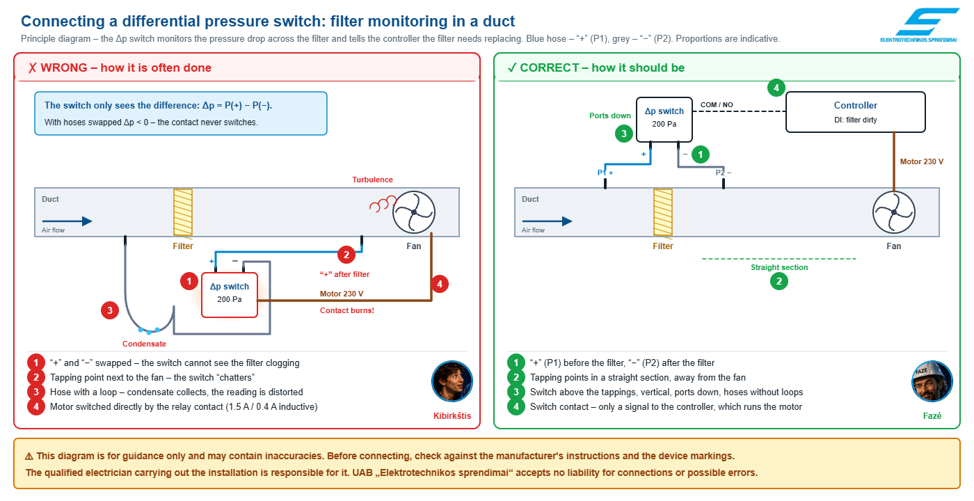 ☝ Click the diagram to open an enlarged version.⚠ The diagram is for guidance only and may contain inaccuracies.
Before connecting, check against the manufacturer’s instructions and the markings on the device. The qualified electrician carrying out the installation is responsible for it. UAB „Elektrotechnikos sprendimai“ accepts no liability for the connection or possible errors.Why – explanation by diagram number
1Tube polarity
✗ “+” connected downstream of the filter, “−” upstream.
✓ “+” (P1) upstream of the filter, where the pressure is higher; “−” (P2) downstream.
Why: The switch changes over when Δp = P1 − P2 reaches the setpoint. With the tubes swapped Δp becomes negative – the filter can clog completely and there will be no signal.
Products: DPR · PSW · connection kit
2Location of measuring points
✗ Measuring point next to a fan, bend or damper.
✓ For filter monitoring – tapping points in a straight duct section, as far as possible from the fan and obstructions.
Why: Near the fan and bends the airflow is turbulent – the pressure fluctuates, the switch “chatters” and the transmitter value is unstable.
Products: connection kits · Pitot kits
3Mounting position and tubes
✗ Switch mounted horizontally below the duct, tube with a downward loop.
✓ Switch above the measuring points, vertical, ports facing down; tubes short and without loops.
Why: Condensate collects in the loop – a water column distorts a measurement of just a few pascals. The mounting position affects the setpoint of a mechanical switch, so follow the position specified by the manufacturer.
Products: Δp switches · transmitters
4Contact load
✗ Fan motor or a large contactor coil switched directly through the switch contact.
✓ The switch contact is only a signal to the controller; the motor is controlled by a controller, frequency inverter or contactor.
Why: A typical Δp switch contact is rated 1.5 A for a resistive load and only 0.4 A for an inductive load. Motor inrush current quickly burns out the contact.
Products: PI controllers · SPS2
⚠ What to check before buying
KibirkštisBefore ordering I always write down these points – then I don’t have to change the range on site.What to check Why it matters Operating Δp and setpoint The setpoint should be in the middle of the range – this determines the model. Is negative pressure needed? For room cascades and extraction choose −125…+125 Pa or a ± pressure gauge. Signal type Contact, 0–10 V, 0–20 mA, PWM or Modbus RTU – it must match the controller input. Power supply 24 V AC/DC (G) or 24 V DC only (F); a mechanical switch needs no power supply. Medium Air – Δp switches and transmitters in Pa; water, compressed air – pressure switches in bar. Environment and IP Outdoors, in a humid section or in the cold – IP65 or higher, temperature limits. Connection parts Nipples, tube, Pitot tube – whether they are included or must be bought separately. ✗ Most common mistakes
Mistake Consequence “+” and “−” tubes swapped The switch never trips; the transmitter shows zero or a negative value. Range too wide (e.g. 0–2000 Pa to measure 50 Pa) The signal barely moves; accuracy and resolution are lost. Setpoint near the range limit The switch trips inaccurately or not at all. Loops and kinks in the tube Condensate or a pinched tube distorts the readings. Filter measuring point next to the fan Unstable readings, false alarms. Motor switched through the switch contact ⚡ Contacts overheat and stick (weld) – risk of fire and failure. 24 V AC connected to a 24 V DC only (F) version ⚡ Device failure.
⚡ Safe installation – Fazė’s advice
- Switch contacts may be connected to 230 V – disconnect the voltage before opening the cover.
- Before working on a ventilation unit, stop the fans and secure them against unexpected start-up.
- Route 24 V control cables and 230 V power cables separately.
- For pressure switches (bar) – relieve the system pressure before disconnecting.
- Test after installation: cover part of the filter – Δp must rise; the switch operates when Δp reaches the setpoint (for the test you may temporarily lower the setpoint).
☝ Elsprendimai.eu recommends: for a single ventilation unit – a Δp switch for each filter and a pressure gauge for visual checks. For building automation – a transmitter with Modbus RTU or a dual transmitter for supply and extract filters. For constant pressure – a PI controller for a fan or damper. Don’t forget the connection kit.Frequently asked questions
Questions from Kibirkštis – a young, curious electrician who dares to ask what others won’t. Answers from Fazė – an experienced engineer.
KibirkštisWhat is the difference between a switch, a transmitter and a controller?
FazėA switch changes over a contact when Δp reaches the setpoint. A transmitter continuously sends the Δp value – 0–10 V, 0–20 mA, PWM or Modbus RTU. A PI controller measures and controls the fan or damper itself to keep the pressure at the setpoint.
KibirkštisWhat setpoint should I use for a filter?
FazėCheck the filter manufacturer’s final pressure drop and set slightly below it so the signal comes in time. Choose the switch so that this setpoint is in the middle of its range.
KibirkštisWhere do I connect “+” and where “−”?
Fazė“+” (P1) goes where the pressure is higher: for filter monitoring – upstream of the filter. “−” (P2) – downstream of the filter. For fan proving, “+” goes on the discharge side and “−” on the suction side.
KibirkštisWhat is the difference between G and F versions?
FazėG – 24 V AC or DC power supply, 3-wire connection. F – 24 V DC only, 4-wire connection with a separate signal negative. Choose according to the controller power supply and signal input.
KibirkštisCan I switch a fan directly with the switch contact?
FazėNo. A typical Δp switch contact is rated 1.5 A for a resistive load and 0.4 A for an inductive load. Use it as a signal to a controller or via an interposing relay or contactor.
KibirkštisCan you help me choose?
FazėYes. Send us the ventilation unit data or the design – we will select switches, transmitters, controllers and accessories. Contact us.Sources
- Sentera Controls – technical data for the HPS, HPD, DPS, SPS2, HPSP, HPSA, DPSP, DPSA, PSW series.
- Manufacturers’ technical data for the DPR, ESLF32, ESLF35, ESLF55, ESLFB series (product pages).
- EN ISO 16890-1 – Air filters for general ventilation.
- EN 16798-3 – Energy performance of buildings, ventilation for non-residential buildings.
Typical pressure values are indicative – final values are specified by the equipment manufacturer or the design. Checked 2026-10-14.
From a filter signal to constant pressure control
Δp switches, transmitters with 0–10 V and Modbus RTU, PI controllers, pressure gauges, pressure switches and connection kits – all in one place. Send us the ventilation unit data or the design: we will select a solution and send you a quote.
Get a quote 1 - 16 of 127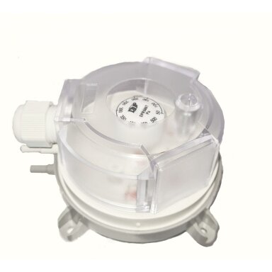
 Differential pressure switch | 20–200 Pa | differential 10 Pa | SPDT | 1.5 A (0.4 A) 250 V AC | IP54 | DPR-200KCode: DPR-200KPrice 18.85 € VAT incl.( 15.58 € VAT excl. )Differential pressure controller with 2 setpoints | 0-6000Pa | 0-10VDC/0-20mA/PWM | Modbus RTU | 24VAC/VDC | IP65 | Sentera Controls | SPS2G-6K0Code: SPS2G-6K0Price 135.01 € VAT incl.( 111.58 € VAT excl. )
210.61 €You save 75.60 €Differential pressure controller with 2 setpoints | 0-2000Pa | 0-10VDC/0-20mA/PWM | Modbus RTU | 24VAC/VDC | IP65 | Sentera Controls | SPS2G-2K0Code: SPS2G-2K0Price 130.56 € VAT incl.( 107.90 € VAT excl. )203.67 €You save 73.11 €Differential pressure controller with 2 setpoints | 0-6000Pa | 0-10VDC/0-20mA/PWM | Modbus RTU | 24VDC | IP65 | Sentera Controls | SPS2F-6K0Code: SPS2F-6K0Price 136.37 € VAT incl.( 112.70 € VAT excl. )212.73 €You save 76.36 €Differential pressure controller with 2 setpoints | 0-2000Pa | 0-10VDC/0-20mA/PWM | Modbus RTU | 24VDC | IP65 | Sentera Controls | SPS2F-2K0Code: SPS2F-2K0Price 137.76 € VAT incl.( 113.85 € VAT excl. )214.91 €You save 77.15 €Differential pressure switch | 50-500Pa | changeover contact | 250VAC | IP54 | Sentera Controls | PSW--500Code: PSW--500Price 19.17 € VAT incl.( 15.84 € VAT excl. )29.90 €You save 10.73 €Differential pressure switch | 50-500Pa | changeover contact | 250VAC | IP54 | with PVC tubes and nozzles | Sentera Controls | PSW--500-PVCCode: PSW--500-PVCPrice 24.55 € VAT incl.( 20.29 € VAT excl. )38.30 €You save 13.75 €Differential pressure switch | 20-200Pa | changeover contact | 250VAC | IP54 | Sentera Controls | PSW--200Code: PSW--200Price 19.17 € VAT incl.( 15.84 € VAT excl. )29.90 €You save 10.73 €Differential pressure switch | 20-200Pa | changeover contact | 250VAC | IP54 | with PVC tubes and nozzles | Sentera Controls | PSW--200-PVCCode: PSW--200-PVCPrice 24.55 € VAT incl.( 20.29 € VAT excl. )38.30 €You save 13.75 €Differential pressure connection kit | aluminium nozzles | PVC tube 2m | up to 10000Pa | Sentera Controls | PSET-QF-200Code: PSET-QF-200Price 11.39 € VAT incl.( 9.41 € VAT excl. )17.76 €You save 6.37 €Differential pressure connection kit | plastic nozzles | PVC tube 2m | up to 10000Pa | Sentera Controls | PSET-PVC-200Code: PSET-PVC-200Price 3.19 € VAT incl.( 2.64 € VAT excl. )4.97 €You save 1.78 €Pitot tube connection kit for measuring air velocity | 150mm | for ducts Ø100-300mm | PVC tube 2m | Sentera Controls | PSET-PTS-200Code: PSET-PTS-200Price 11.08 € VAT incl.( 9.16 € VAT excl. )17.29 €You save 6.21 €Pitot tube connection kit for measuring air velocity | 250mm | for ducts Ø150-500mm | PVC tube 2m | Sentera Controls | PSET-PTL-200Code: PSET-PTL-200Price 13.20 € VAT incl.( 10.91 € VAT excl. )20.59 €You save 7.39 €Price 176.53 € VAT incl.( 145.89 € VAT excl. )275.37 €You save 98.84 €Differential pressure PI controller for fans | 0-4000Pa | 0-10VDC/0-20mA/PWM | Modbus RTU | 24VAC/VDC | IP65 | Sentera Controls | HPSPG-4K0Code: HPSPG-4K0Price 148.77 € VAT incl.( 122.95 € VAT excl. )232.08 €You save 83.31 €Differential pressure PI controller for fans | 0-2000Pa | 0-10VDC/0-20mA/PWM | Modbus RTU | 24VAC/VDC | IP65 | Sentera Controls | HPSPG-2K0Code: HPSPG-2K0Price 144.74 € VAT incl.( 119.62 € VAT excl. )225.81 €You save 81.07 €


