


Wireless industrial crane control panels | remote control systems
-
Wireless crane remote controls – an engineer’s way to choose
A radio remote replaces the buttons of a wired pendant, but the crane is still switched by contactors. That is why the remote is chosen in the same order as the control circuit is designed: 1) motions and speeds → number of receiver outputs, 2) control circuit voltage → receiver supply, 3) safety circuit – STOP, START, loss of link, 4) radio frequency, range and how many cranes work in one area, 5) environment – IP rating. Only then the specific model.
ℹ Selection✓ Benefit⚠ Check⚡ SafetyRadio linkLOTO
How a radio control system works
1Transmitter
Operator unit with buttons or levers, battery powered→2Radio channel
Coded signal: the receiver responds only to its own transmitter→3Receiver
Mounted in the crane cabinet, powered from the control voltage, has relay outputs→4Contactors
Relay outputs switch the contactor coils – direction, speed, main contactor→5Motors
Hoist, trolley and bridge motors, brakes, limit switchesℹ The receiver relays switch only the control circuit. Motor current is switched by contactors, and limit switches and overload limiters remain in the circuit – a radio remote does not replace them.
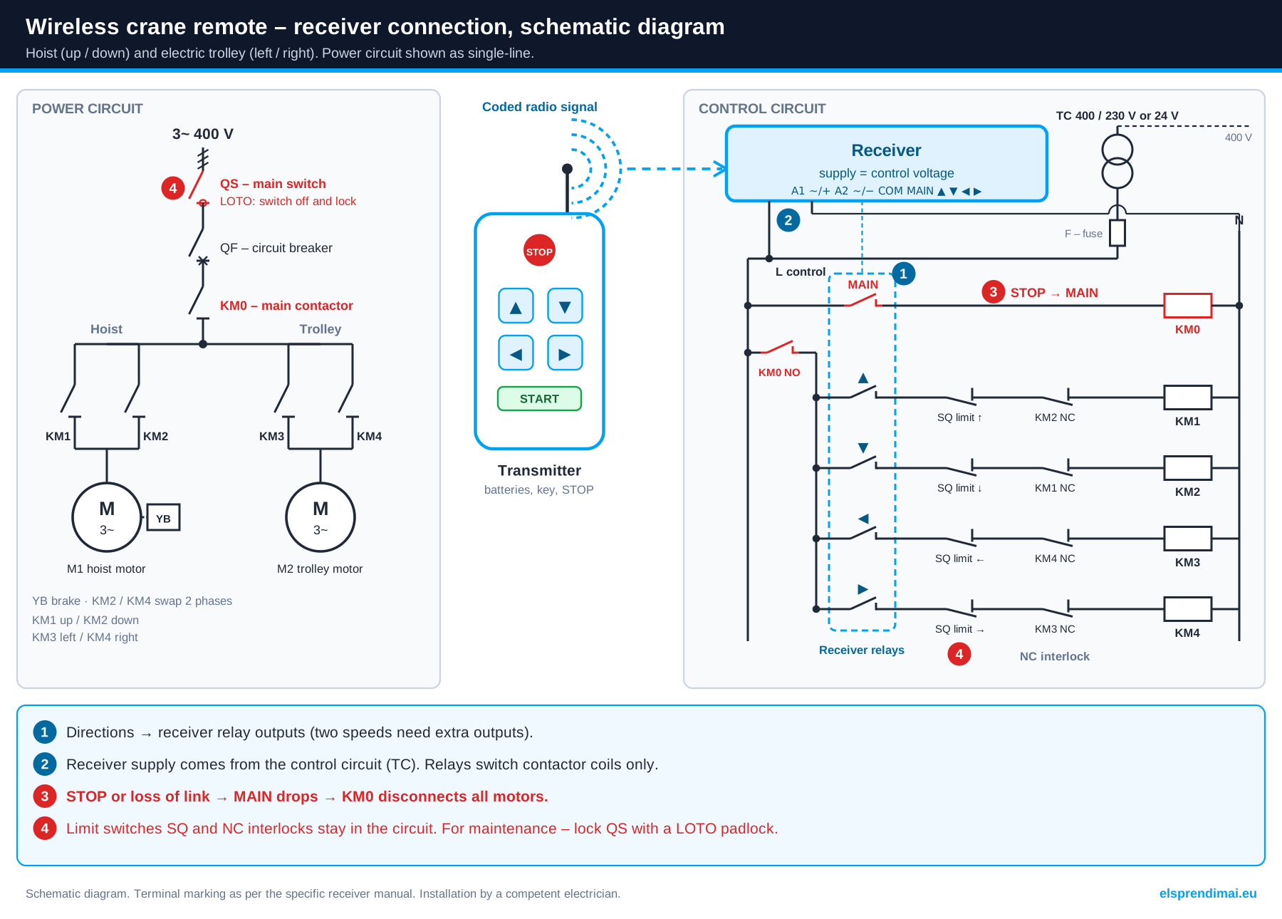
Schematic diagram: receiver relays switch contactor coils, STOP de-energises main contactor KM0. Click to enlarge.
⚠ This diagram is for guidance only and may contain inaccuracies. Before connecting, check against the manufacturer's instructions and the device markings.
The qualified electrician carrying out the installation is responsible for it. UAB „Elektrotechnikos sprendimai“ accepts no liability for connections or possible errors.1. Motions and speeds → receiver outputs
Each direction is a separate receiver output. Two-speed control needs additional outputs for fast speed, and the main contactor needs a MAIN output. So count the directions first.
Equipment Directions Buttons on remote Outputs, 1 speed Outputs, 2 speeds Electric hoist 2 (up / down) 2 2 + MAIN up to 4 + MAIN Hoist with electric trolley 4 4 4 + MAIN up to 8 + MAIN Overhead or jib crane 6 6 6 + MAIN up to 12 + MAIN Crane with auxiliary hoist or extra functions 8 or more 8–12 or 18 8 + MAIN and extra per circuit ℹ On two-speed remotes the button has two steps: the first gives slow speed, the second fast speed. Whether the receiver has a separate fast-speed output for each direction or a common speed output depends on the model – compare it with the crane circuit. A horn, lighting or magnet needs extra buttons and outputs.
2. Control circuit voltage → receiver supply
The receiver is powered from the same circuit that feeds the contactor coils. Check the coil marking of the contactors or the control transformer – that is the receiver voltage you need.
Control circuit Receiver supply Models Unknown, or several cranes with different voltages Universal 12–440 V or 24–440 V AC/DC ES-F21-2SE, ES-F21-4SE, ES-F21-E1B(H), ES-F23-6D, ES-F24-8D 230 V AC 230 V AC ES-LD-BC2, ES-LD-BC4, ES-ML-K2, ES-ML-K4, ES-F21-T2S 100–240 V AC (mains supply) 100–240 V AC ES-Q5000, ES-E1738-315B 24 V AC/DC or 12–24 V AC/DC 12–24 V AC/DC or 24 V AC/DC ESF24-6SHS-6, EL-F24-60-24 12 / 24 V DC – mobile machinery, hydraulics 12 V DC or 24 V DC ES-YLB12, ES-YLB24, ES-WRC685, ES-CRC687, ES-BT500, ES-D1 ⚠ The relay contact current (e.g. 5 A, 10 A, 15 A) is for contactor coils, not for the motor. If the crane has no control transformer and the coils run on 400 V, choose a receiver whose range covers 400 V (24–440 V AC/DC).
⚡ 3. Safety circuit – STOP, START and loss of link
In wireless control, safety comes not from the button itself but from how the receiver outputs are wired into the circuit. The main contactor (MAIN) must be in series with all motions.
Function How it works What it means in the circuit Emergency STOP When pressed, the receiver drops the MAIN output MAIN de-energises the main contactor – all motions stop, not just one direction START MAIN is energised only after START The crane does not start by itself when the transmitter is switched on Loss of link With no signal the receiver switches its outputs off The crane stops if the battery runs flat or the operator leaves the range – must be tested at commissioning Opposite-direction interlock The receiver does not energise up and down at the same time Electrical interlocking with contactor NC contacts is still required Address code The receiver accepts only its own transmitter code Several cranes in one hall do not control each other Key on transmitter The transmitter cannot be switched on without the key Unauthorised persons cannot use the crane ⚡ Requirements for the electrical equipment of hoisting machines (EN 60204-32) for cableless control: on loss of the link the crane must stop automatically, and STOP must de-energise the main contactor. This is tested every time a receiver is installed or replaced.
4. Radio link – frequency, range, several cranes
Frequency and operating range depend on the remote series. The manufacturer’s range is given for open space – in a production hall with metal structures it is shorter.
Frequency / system Range Suitable for Models 868 MHz 150–250 m Hoists, hoists with trolleys, halls with several cranes ES-F21-2SE, ES-F21-4S+, ES-LD-BC4, ES-ML-K4 433 MHz up to 100 m Overhead cranes, two-speed remotes, two-transmitter systems ES-F23-6D, ES-F24-8D, ES-Q1800 315 / 433 MHz up to 100 m Joystick remotes, compact sets EL-F24-60, ES-Q5000, AK-C211008 Long-range systems up to 225–500 m Heavy and hydraulic machinery, large yard cranes ES-ECD-Q5000, ES-YLB12, ES-YLB24 - Several cranes in one area – each transmitter–receiver pair must have a different address code; with many remotes, use different channels as well.
- Antenna – mount the receiver or its antenna so that the metal cabinet and structures do not block the signal.
- Interference – keep the receiver and its wiring away from frequency inverters and power cables.
- Batteries – the transmitter is battery powered; a flat battery shortens the range, so replace batteries in time.
⚠ In the EU, short-range radio devices mostly use the 433 MHz and 868 MHz bands. For 315 MHz models, check before use that the frequency is permitted in your country.
5. Environment – transmitter IP rating
The first digit of the IP code indicates protection against dust, the second against water. All transmitters in this group are dust-tight (6); they differ in water protection.
IP rating Dust Water Suitable for IP65 6 – dust-tight 5 – jet from a 6.3 mm nozzle Workshops, warehouses, dusty areas IP66 6 – dust-tight 6 – powerful jet from a 12.5 mm nozzle Outdoor cranes, rain, washing IP67 6 – dust-tight 7 – temporary immersion up to 1 m Construction sites, loading yards IP68 6 – dust-tight 8 – continuous immersion (conditions set by the manufacturer) Ports, heavy machinery, harsh environments ⚠ The IP rating applies only with the battery cover tightly closed and an undamaged gasket. The receiver is usually mounted in a cabinet or has its own enclosure IP – check it separately.
Quick selection by situation
Situation What to choose Models Electric hoist – lifting and lowering only 2-button remote, 1 speed ES-F21-2SE, ES-LD-BC2, ES-F21-2S+ Hoist with electric trolley (4 directions) 4-button remote ES-F21-4SE, ES-F21-4S+, ES-ML-K4 Overhead or jib crane – 6 directions 6-button remote ES-F21-E1B(H), ES-F23-6D, ES-Q606 Two-speed motors or a frequency inverter Two-speed remote with two-step buttons ES-F23-6D, ES-F24-8D, ES-24-8D, ES-24-12D Auxiliary hoist, horn, lighting 8–12-button remote ES-24-10D, ES-24-12S, ES-F23-BB Two operators or two control stations 2 transmitters + 1 receiver ES-Q1800, F21-2S-b3ce Many functions at once – manipulators, special machinery Joystick (lever) remote EL-F24-60, ES-Q5000, ES-WRC685 Mobile hydraulic machinery 12 V or 24 V DC Remote for hydraulic machinery ES-YLB12, ES-YLB24 Emergency STOP must be clearly visible Remote with mushroom-head STOP ES-F21-2S+, ES-F21-4S+, EL-F24-60 A cable is acceptable, no radio needed Wired pendant Wired crane pendants Remote series in this group
Series Buttons Speeds Radio Receiver supply IP Models Compact 868 MHz 2 / 4 / 6 1 868 MHz, 150–250 m 12–440 V, 24–440 V AC/DC or 230 V AC IP65–IP66 ES-F21-2SE, ES-F21-4SE, ES-F21-E1B(H), ES-F21-T2S, ES-LD-BC2, ES-LD-BC4, ES-ML-K2, ES-ML-K4 With mushroom-head STOP 2 / 4 1 868 MHz, up to 250 m 24–440 V AC/DC depends on model ES-F21-2S+, ES-F21-4S+ Compact F21, 10 A relays 2 / 4 1 / 2 depends on model depends on model IP65–IP66 ES-21-2S, ES-21-4S, ES-21-4D F21, 100 m 2 / 6 1 up to 100 m 24–440 V AC/DC IP65 EL-F21-2S-TX, ES-F21-E1-TX, F21-E1B-TX Two-speed 2 / 6 / 8–12 2 433 MHz, up to 100 m (F23, F24) 24–440 V AC/DC or 230 V AC IP65 ES-F23-6D, ES-F24-8D, ES-Q606, ES-F21-E2B-8, ES-24-8D, ES-24-10D, ES-24-12D, LCC-202 Multi-button, single speed 6–12 1 depends on model 12–24 V AC/DC, 12 V or 24–440 V AC/DC IP65 / IP68 ES-24-8S, ES-24-10S, ES-24-12S, ES-F23-BB, ES-ML-K6, ESF24-6SHS-6 2 transmitters + 1 receiver 18 / 6 channels 1 433 MHz, up to 100 m depends on model IP65 / IP66 ES-Q1800, F21-2S-b3ce Joystick (lever) 6 buttons + levers; 4–9 levers – 315 / 433 MHz, 2,4 GHz, 100–225 m 12–440 V; 12 / 24 / 24–48 V AC/DC; 24 V DC; 100–240 V AC IP66–IP68 EL-F24-60, EL-F24-60-12, EL-F24-60-24, EL-F24-60-48, ES-ECD-Q5000, ES-Q5000, ES-D1, ES-WRC685, ES-WRC624, ES-CRC687, ES-BT500 For hydraulic machinery 4 directional joysticks – up to 500 m 12 V DC / 24 V DC – ES-YLB12, ES-YLB24 Compact 315 / 433 MHz and spare transmitters 2 / 4 1 315 / 433 MHz 85–250 V / 100–240 V AC – AK-C211008, AK-C211009, ES-E1738-315B ℹ Parameters are taken from the product pages; where it says “depends on model”, see the product description for exact data. AK-C211009 is a transmitter without a receiver: it only works with a compatible receiver of the same system.
✗ Most common mistakes
Mistake Consequence Receiver chosen without matching the contactor coil voltage The receiver does not start or burns out Motor connected directly to the receiver relays Relay contacts burn, the load may move uncontrolled ⚡ STOP / MAIN wired into one direction circuit only Emergency stop does not cut all motions ⚡ Directions or phase sequence swapped after connection “Up” lowers, the upper limit switch does not protect Loss of link not tested at commissioning With a flat battery the crane may not stop Two remotes with the same code in one hall One remote controls another crane Too few receiver outputs for a two-speed crane The second speed step or an extra function does not work Receiver or antenna in a metal cabinet next to a frequency inverter Shorter range, intermittent link ⚡ Safe installation and commissioning
- ⚡ The receiver must be wired into the crane circuit by a competent electrician, with the power switched off and absence of voltage verified.
- The receiver supply is taken from the control circuit and protected according to the manufacturer’s instructions.
- The MAIN output is wired in series with the main contactor coil; the direction contactors are interlocked with NC contacts.
- Limit switches and overload limiters remain in operation – do not bypass them.
- Follow the requirements for electrical equipment of hoisting machines (EN 60204-32) and the applicable lifting equipment maintenance rules.
Commissioning test – without load:
- Each button moves the crane in the direction marked on the remote.
- STOP stops all motions; after releasing STOP the crane does not start without START.
- During a motion, switch the transmitter off or remove the batteries – the crane must stop.
- Limit switches operate in both directions.
- With several cranes in the hall – each remote controls only its own crane.
LOTO – before crane and hoist maintenance
A switched-off transmitter, a pressed STOP or a removed key is not safe energy isolation. The receiver, contactors, motor and brake remain live.
- Stop the crane and lower the load.
- Switch off the crane main (incoming) switch.
- Lock it with a personal LOTO padlock and attach a warning tag; when several people work – use a multi-lock hasp.
- Verify absence of voltage, and only then start work.
Padlocks, hasps and tags – LOTO lockout devices. Other equipment – work safety.
Alternatives and related components
What you need Where to find it Simple cable control, no batteries Wired crane pendants “ELCA” radio remotes “ELCA” wireless remotes Joysticks and accessories for remotes Joysticks | accessories Directions, main contactor Contactors and starters Hoisting and travel limiting Limit switches Building your own control station Control push buttons Safe maintenance LOTO lockout devices The whole crane control group Hoists | crane control pendants | hoist control Frequently asked questions
How many buttons does my crane need?
Count the directions: a hoist needs 2, a hoist with a trolley 4, an overhead crane 6. For two-speed motors choose a two-speed remote, for extra functions – 8–12 buttons.
Can a wireless remote be fitted to an existing hoist or crane?
Yes. The receiver is connected to the existing contactors in place of the wired pendant. Check the contactor coil voltage, the number of directions and speeds, and the space for the receiver in the cabinet.
What receiver voltage do I need?
The same voltage that feeds the contactor coils. If you do not know it or have several different cranes, choose a universal 12–440 V or 24–440 V AC/DC receiver.
Can several remotes work in one hall?
Yes, if each transmitter–receiver pair has its own address code. With many cranes, choose different channels as well.
What happens if the transmitter battery runs flat?
The receiver stops receiving the signal and must switch its outputs off – the crane stops. Test this when commissioning the system.
Can the wired pendant be kept as a backup?
Yes, if the circuit provides for it – usually via a “wired / radio” selector switch. Such a circuit must be designed and tested by a specialist.
Does a switched-off remote protect during maintenance?
No. For maintenance, switch off the crane main switch and lock it with a LOTO padlock.
In short
- Directions and speeds determine the number of buttons and receiver outputs.
- Receiver supply = contactor coil voltage; the relays switch coils, not the motor.
- STOP and loss of link must de-energise the main contactor – test at commissioning.
- 868 MHz – up to 250 m, 433 MHz – up to 100 m; several cranes – different codes.
- For maintenance – lock the main switch with a LOTO padlock.
Tell us the crane type, directions and speeds, the contactor coil voltage and, if possible, send a photo of the circuit – we will select the remote, receiver and contactors. Contact us.
 1 - 16 of 48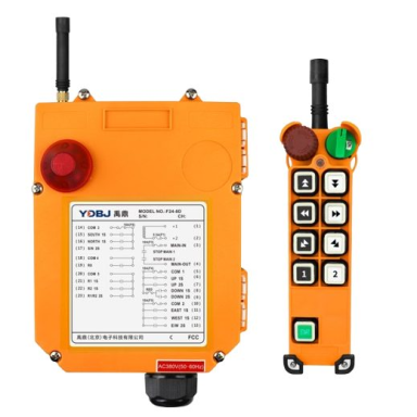
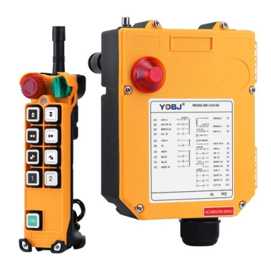
 Wireless crane remote control | 8 buttons + START/STOP | 2 speeds | 433 MHz | 24–440 V AC/DC | IP65 | ES-F24-8DCode: ES-F24-8DPrice 380.17 € VAT incl.( 314.19 € VAT excl. )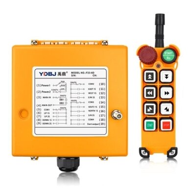
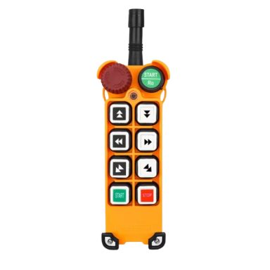 Wireless crane remote control | 6 buttons + START/STOP | 2 speeds | 315/433 MHz | 24–440 V AC/DC | IP65 | ES-F23-6DCode: ES-F23-6DPrice 336.72 € VAT incl.( 278.28 € VAT excl. )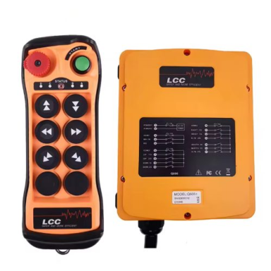
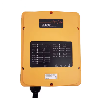 Wireless crane remote control | 6 buttons + START/STOP | 2 speeds | 420–450 MHz | 12–460 V AC/DC | IP65 | ES-Q606Code: ES-Q606Price 375.27 € VAT incl.( 310.14 € VAT excl. )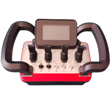
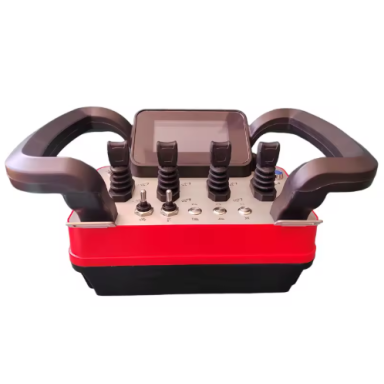 Wireless remote control for hydraulic machinery | 4 levers | LCD display | 24 V DC | up to 500 m | IP67 | ES-YLB24Code: ES-YLB24Price 3123.87 € VAT incl.( 2581.71 € VAT excl. )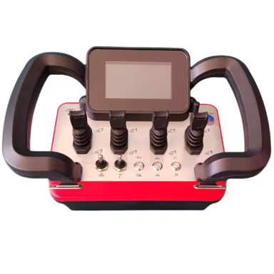
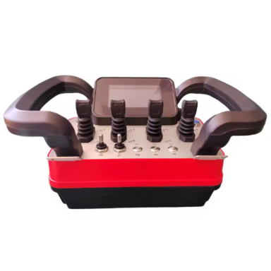 Wireless remote control for hydraulic machinery | 4 levers | LCD display | 12 V DC | up to 500 m | IP67 | ES-YLB12Code: ES-YLB12Price 3123.87 € VAT incl.( 2581.71 € VAT excl. )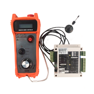
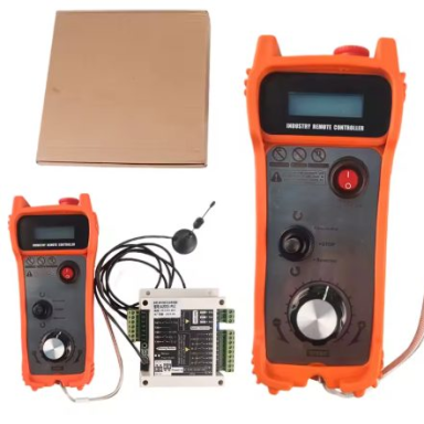 Wireless crane remote control | 2 transmitters + receiver | 6 channels | up to 100 m | 12/24 V DC, 36/48/220/380 V AC | IP66 | F21-2S-b3ceCode: F21-2S-b3cePrice 127.05 € VAT incl.( 105.00 € VAT excl. )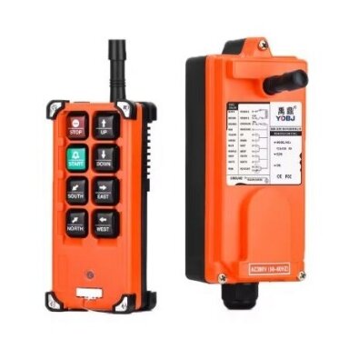
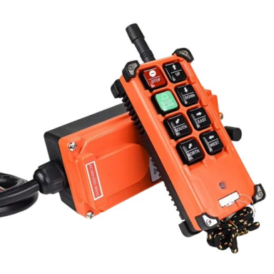 Wireless crane remote control | 6 buttons + START/STOP, 2×4 keypad | 1 speed | 24–440 V AC/DC | IP65 | F21-E1B-TXCode: F21-E1B-TXPrice 130.00 € VAT incl.( 107.44 € VAT excl. )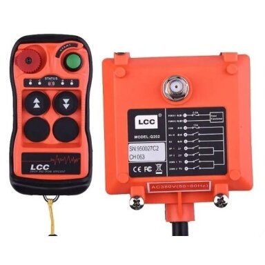
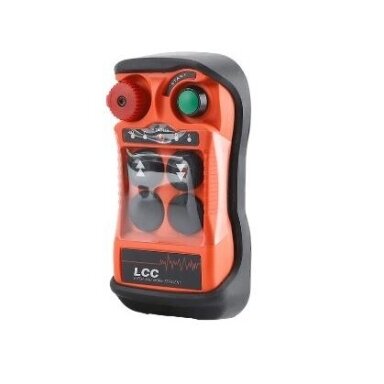 Wireless crane remote control | 2 two-step buttons + START/STOP | 2 speeds | 230 V AC | IP65 | LCC-202Code: LCC-202Price 116.76 € VAT incl.( 96.50 € VAT excl. )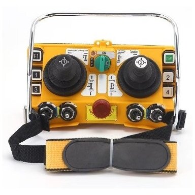
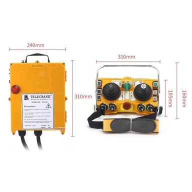 Wireless crane remote control | 2 joysticks | 5 speeds | receiver 12 V AC/DC | 15 A relays | EL-F24-60-12Code: EL-F24-60-12Price 772.63 € VAT incl.( 638.54 € VAT excl. )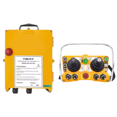
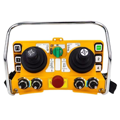 Wireless crane remote control | 2 joysticks | 5 speeds | 315/433 MHz | 12–440 V AC/DC | EL-F24-60Code: EL-F24-60Price 773.19 € VAT incl.( 639.00 € VAT excl. )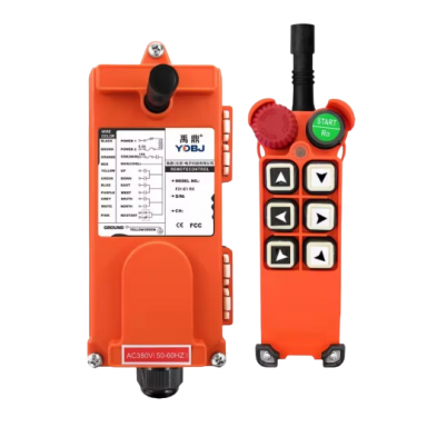
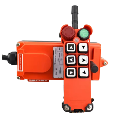 Wireless crane remote control | 6 buttons + START + mushroom STOP | 1 speed | 24–440 V AC/DC | IP65 | ES-F21-E1-TXCode: ES-F21-E1-TXPrice 117.98 € VAT incl.( 97.50 € VAT excl. )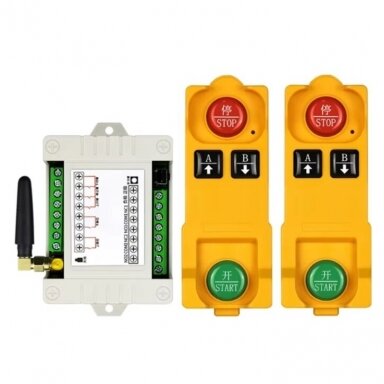
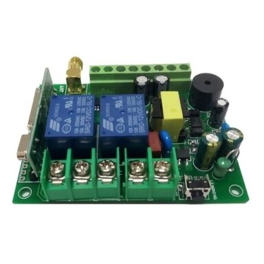 Wireless crane remote control | 2 transmitters + receiver | 2 buttons + START/STOP | 1 speed | 315 MHz | 100–240 V AC | ES-E1738-315BCode: ES-E1738-315BPrice 38.12 € VAT incl.( 31.50 € VAT excl. )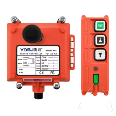
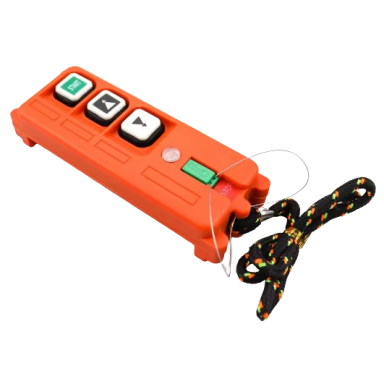 Wireless crane remote control | 2 buttons + START, magnetic key | 1 speed | 24–440 V AC/DC | IP65 | EL-F21-2S-TXCode: EL-F21-2S-TXPrice 93.17 € VAT incl.( 77.00 € VAT excl. )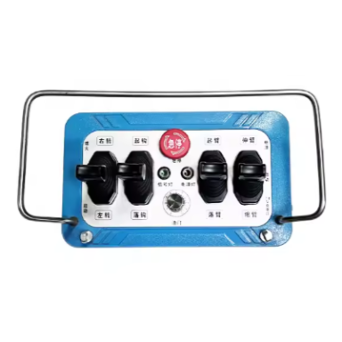
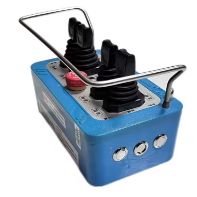 Price 2178.00 € VAT incl.( 1800.00 € VAT excl. )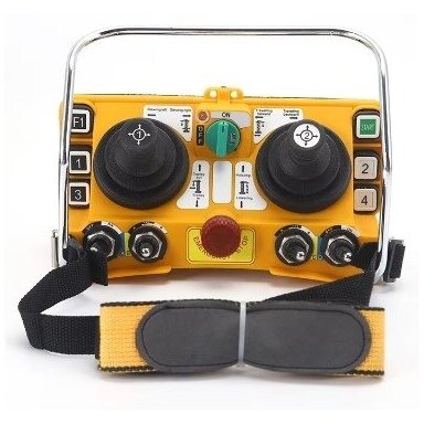
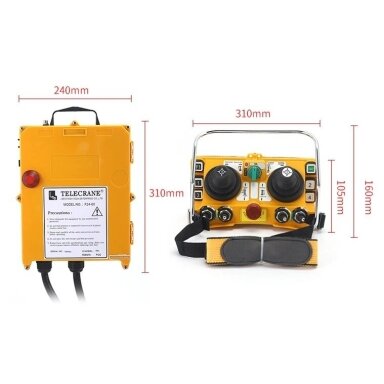 Wireless crane remote control | 2 joysticks | 5 speeds | receiver 24 V AC/DC | 15 A relays | EL-F24-60-24Code: EL-F24-60-24Price 772.63 € VAT incl.( 638.54 € VAT excl. )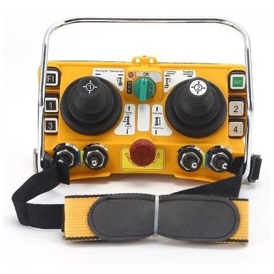
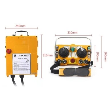 Wireless crane remote control | 2 joysticks | 5 speeds | receiver 24–48 V AC/DC | 15 A relays | EL-F24-60-48Code: EL-F24-60-48Price 772.63 € VAT incl.( 638.54 € VAT excl. )


